Three-hole-site synchronous drilling-type advanced geological drilling device

A drilling device and geology technology, applied in supporting devices, drilling equipment, directional drilling, etc., can solve problems such as affecting the progress of tunnel construction, difficult to ensure drilling quality, and many manpower and material resources, and achieve high practical value and easy front and rear adjustment. , the effect of reducing labor intensity

Inactive Publication Date: 2016-06-15
XIAN YUEFU ELECTRICAL TECH
View PDF0 Cites 2 Cited by
  • Summary
  • Abstract
  • Description
  • Claims
  • Application Information

AI Technical Summary

Problems solved by technology

Nowadays, when carrying out advanced geological drilling, the drilling is mainly carried out by manually controlling the horizontal drilling rig. However, due to the long length of the advanced geological drill pipe, the actual operation is inconvenient, and more manpower and material resources are required. The drilling efficiency is low and the labor intensity is low. Large, time-consuming and labor-intensive, and the drilling quality is not easy to guarantee
In addition, when performing advanced geological drilling nowadays, most of the advanced geological drilling holes are drilled one by one. Usually, the number of advanced geological drilling holes drilled is three, and the manpower required to drill three drilling holes is The material resources are quite large, and the required construction period is long, which greatly affects the progress of the tunnel construction

Method used


Image

  • Three-hole-site synchronous drilling-type advanced geological drilling device
  • Three-hole-site synchronous drilling-type advanced geological drilling device
  • Three-hole-site synchronous drilling-type advanced geological drilling device

Examples


Embodiment Construction

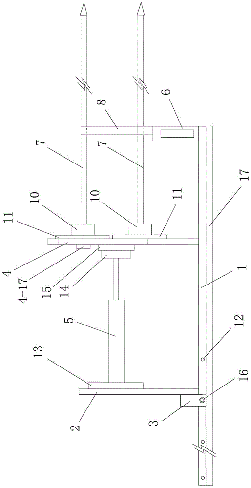
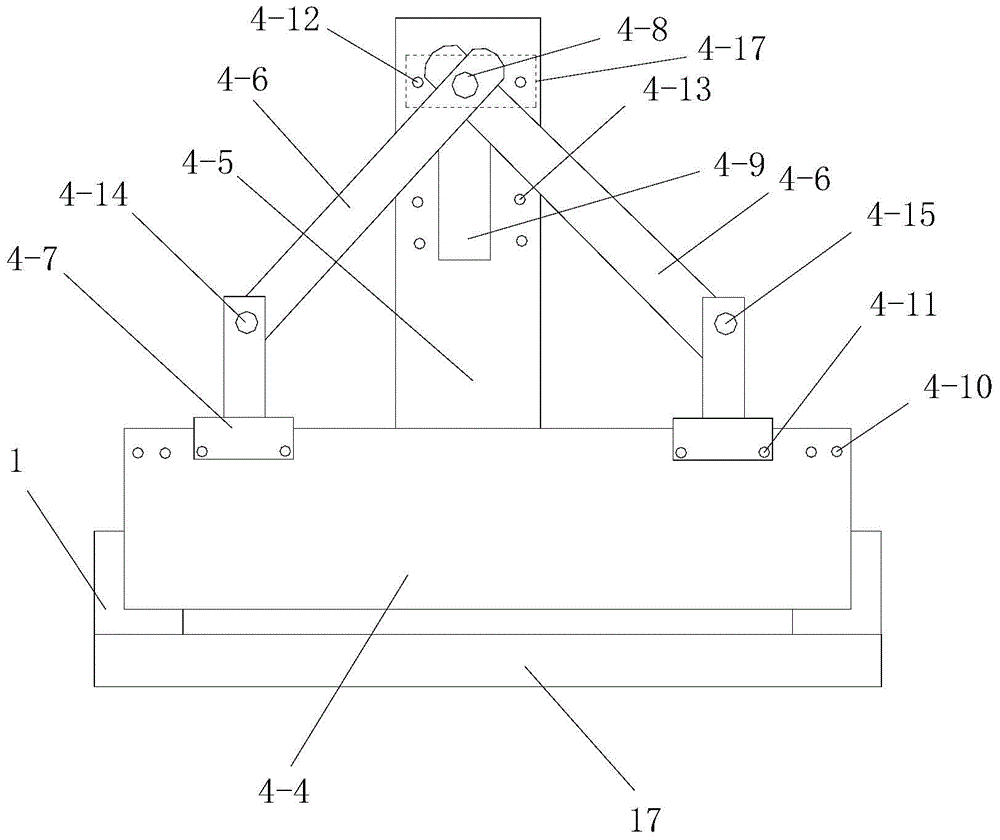
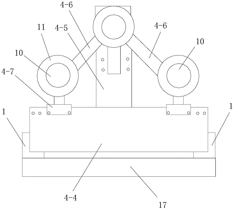
[0035] Such as figure 1 , figure 2 and image 3As shown, the present invention includes a horizontal workbench 17 located at the rear side of the tunnel face under construction, two horizontal steel rails 1 respectively installed on the left and right sides of the upper part of the horizontal workbench 17, and moving back and forth along the two horizontal steel rails 1 The rear push frame 2, the rear limit frame 3 that is clamped on the two horizontal rails 1, the horizontal sliding frame 4 that slides horizontally along the two horizontal rails 1, and promotes the horizontal sliding frame 4 a hydraulic cylinder 5 for horizontal sliding and a front-end support platform 6 positioned at the front ends of the two horizontal rails 1. The hydraulic cylinder 5 is arranged horizontally, the cylinder rear end of the hydraulic cylinder 5 is fixed on the rear push frame 2 and the front end of the piston rod is fixed on the horizontal sliding frame 4; the two horizontal rails 1 are ...


PUM


Abstract

The invention discloses a three-hole-site synchronous drilling-type advanced geological drilling device. The three-hole-site synchronous drilling-type advanced geological drilling device comprises a horizontal workbench, two horizontal steel rails, a back-side push rack, a back limiting rack snapped onto the two horizontal steel rails, a horizontal sliding rack sliding along the two horizontal steel rails, a hydraulic cylinder pushing the horizontal sliding rack to slide and a front-end support table located at the front ends of the two horizontal steel rails. The horizontal sliding rack comprises a rectangular support, a vertical installation board installed above the middle of the rectangular support, two oblique connecting rods installed above the rectangular support on the left and right sides and two horizontal sliding seats moving along the upper part of the rectangular support from the left to the right. An adjustable triangular support is formed by the two oblique connecting rods and the two horizontal sliding seats. Three horizontal drilling rigs are respectively installed at three vertexes of the rectangular support of the adjustable triangular support. The three-hole-site synchronous drilling-type advanced geological drilling device has following beneficial effects: the three-hole-site synchronous drilling-type advanced geological drilling device is simple in structure, reasonable in design, easy and convenient in application and fine in application effect; and the three horizontal drilling rigs are driven to move back and forth during a drilling process so that three-hole-site synchronous drilling is achieved.

Description

technical field [0001] The invention relates to a drilling device, in particular to a three-hole position synchronous drilling type advanced geological drilling device. Background technique [0002] Advanced geological prediction is to make advanced prediction of the surrounding rock and formation conditions in front of the tunnel face during tunnel excavation. There are many geophysical prospecting methods commonly used in advanced geological prediction, and mechanical drilling is a main method of advanced geological prediction. Mechanical drilling is to use advanced geological drill pipes to drill in several parts of the tunnel section, and determine the nature of the surrounding rock in front according to the rock and soil structure, structure and hydrogeology in the drill pipes. In actual mechanical drilling, three positions of the tunnel section are generally taken, namely the upper middle part, the left side and the right side of the tunnel section, and the surroundin...

Claims


Application Information

Patent Timeline
Patent Type & Authority Applications(China)
IPC IPC(8): E21B7/04E21B15/04
Inventor 曹文惠
Owner XIAN YUEFU ELECTRICAL TECH
Why Eureka
Try Eureka