Well-killing method after gas drilling blowout

A gas drilling and well killing technology, which is applied in the fields of liquid/gas jet drilling, wellbore/well parts, earthwork drilling and production, etc. It can solve the problems such as the difficulty of establishing a well killing fluid column, and achieve easy well killing steps and easy operation. Less demanding, the effect of applying wellhead back pressure

Active Publication Date: 2016-06-15
CHINA PETROCHEMICAL CORP +3
View PDF8 Cites 7 Cited by
  • Summary
  • Abstract
  • Description
  • Claims
  • Application Information

AI Technical Summary

Problems solved by technology

When gas drilling encounters a high-yield gas layer, after injecting the killing fluid, due to the complex multiphase flow in the well, it becomes difficult to establish a killing fluid column in the well. At present, there is no systematic well killing method suitable for gas drilling, so it has become a well A difficult point in the field of control

Method used


Image

  • Well-killing method after gas drilling blowout
  • Well-killing method after gas drilling blowout
  • Well-killing method after gas drilling blowout

Examples


Embodiment Construction

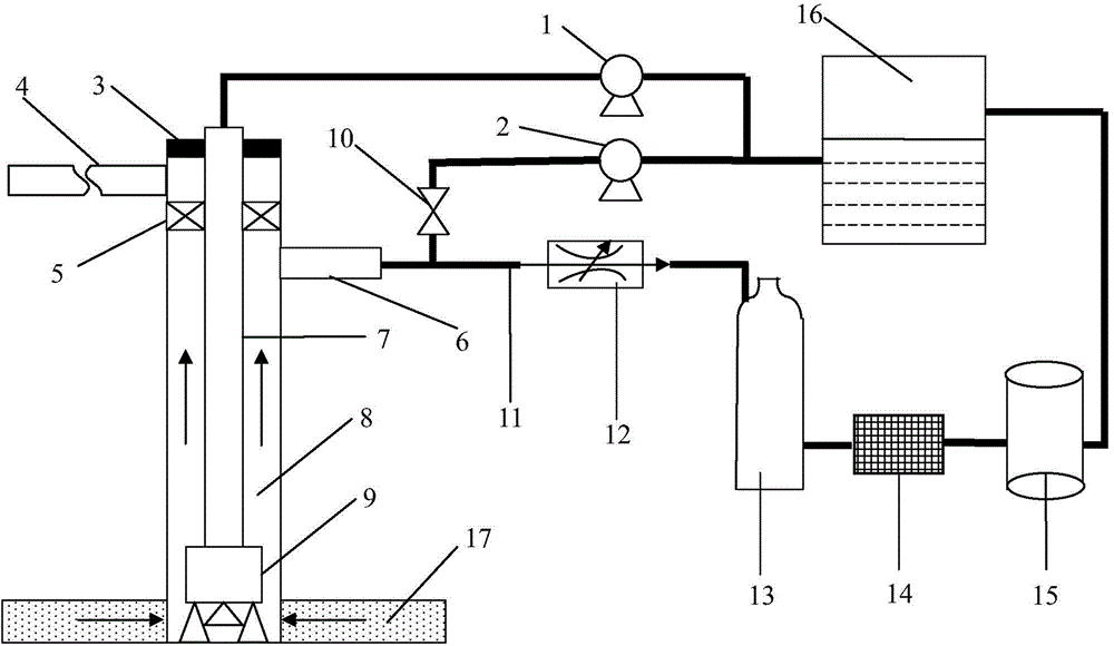
[0029] Attached below figure 1 First, the connection structure of the components and equipment involved in the present invention will be described.

[0030] After drilling into a gas layer, first remove the air compressor and other equipment used in gas drilling to establish figure 1 The connection method shown. The first circulation process is: connect the conventional drilling pump 1 to the mud pool 16 and the wellhead drilling tool 7, and the drilling pump 1 pumps the drilling fluid in the mud pool 16 into the drilling tool 7, and then carries the formation gas into the ring after passing the bottom hole bit 9 Air 8, because the wellhead blowout preventer group 5 is closed, the gas-liquid two-phase flow in the annulus 8 enters the choke manifold 11 through the four-way 6, and the gas-liquid two-phase flow enters the gas-liquid separation after being throttled by the throttle valve 12 After the vibrating screen 14 and the vacuum deaerator 15 are processed, the drilling fluid ...


PUM


Abstract

Provided is a well-killing method after gas drilling blowout. The method comprises following steps: installing a conventional drilling pump and a throttle manifold; connecting the other pressure-regulating pump to a valve of the throttle manifold; calculating allowable pressure of the maximum wellhead; regulating wellhead pressure to the allowable pressure of maximum wellhead by the throttle valve and by connecting the pressure-regulating pump of the throttle manifold; opening the drilling pump for well killing; recording the time well killing liquid takes to reach a drill bore and resultant annulus pressure of a hydrostatic column; and determining relations of pressure of throttle valve and pressure of the hydrostatic column and formation pressure in order to decide the throttle pressure regulation or redesign of well killing. The well-killing method after gas drilling blowout is very suitable for a working condition without any drilling fluid in a well so that the problem that scrubbed gas is throttled with difficulty during the initial phase of well killing is effectively solved. Therefore, establishment of pressure of the hydrostatic column for killing fluid in a shaft is accelerated and well-killing success is achieved. The well-killing method after gas drilling blowout does not need special equipment, is easily operated and suitable for on-site application.

Description

Technical field [0001] The invention relates to a method for killing a well after gas drilling encounters a high-yield gas layer, and belongs to the technical field of oil drilling well control. Background technique [0002] With the rapid development of the national economy, my country's demand for and dependence on oil and gas energy is increasing day by day. At present, traditional mud drilling is the most mature application in oil drilling. It uses conventional drilling fluids to keep the bottom hole pressure slightly higher than the formation pressure for drilling. The mechanical drilling speed is slow, which causes damage to the pay zone and affects subsequent oil (gas) production. It is difficult to find shortcomings such as new production layers. Underbalanced drilling can effectively solve this shortcoming, especially in gas drilling, which uses gas as a circulating medium, which can effectively break the rock while avoiding the pollution of the reservoir and is benefic...

Claims


Application Information

Patent Timeline
Patent Type & Authority Applications(China)
IPC IPC(8): E21B33/03E21B7/18E21B21/08
Inventor 公培斌李宗清陈永明朱焕刚王树江宋荣荣曹强康波宋中文杨俊锋赵亚坤
Owner CHINA PETROCHEMICAL CORP
Why Eureka
Try Eureka