Exhaust Treatment device Facilitating Through-Wall Flow

a technology of exhaust treatment device and through-wall flow, which is applied in the direction of machines/engines, mechanical equipment, separation processes, etc., can solve the problems of difficult reduction of nox tip-in spikes, significant degradation of diesel fuel economy, and low nox emission level of scrs, etc., and achieves the effect of better managemen

Inactive Publication Date: 2007-06-07
FORD GLOBAL TECH LLC
View PDF25 Cites 20 Cited by
  • Summary
  • Abstract
  • Description
  • Claims
  • Application Information

AI Technical Summary

Benefits of technology

[0008] Embodiments include an exhaust treatment device having a layered substrate made of a thin metallic mesh with washcoated fibers or fleece interposed adjacent layers to facilitate trans-layer migration of exhaust flow through corresponding openings of the substrate mesh. The exhaust treatment device may include generally parallel substrate layers to form secondary channels or layers containing relatively fewer (or no) fibers per unit volume with reduced back pressure and greater flow velocities and primary channels containing relatively greater fiber density to increase surface area for chemical and physio adsorption, reduce flow velocities, and increase exhaust flow / fiber interaction with primary channels being at least partially open at both upstream and downstream ends. Secondary channels may also be open at both upstream and downstream ends, or may be substantially closed or blocked at one end. Various embodiments may include secondary channels that may be substantially closed or blocked using a washcoat material to partially or completely fill the secondary channels at one end and / or to provide flow restriction in the primary channels to increase through-wall flow of exhaust.
[0009] Embodiments may also include layers with a length that is more than 1.5 times greater than the diameter of the substrate. Embodiments may have the number of channels in the first group substantially the same as the number of channels in the second group, with the first and second groups having the same geometry, such as triangular or square cross-sectional geometries. The first and second groups of channels may have similar cross-sectional geometries of different size to improve the exhaust gas diffusion while minimizing effective back pressure. Alternatively, the number of channels in the first group may be greater than the number of channels in the second group with the first and second groups having a hexagonal cross-sectional geometry, for example. The channels may be square in cross section and each of the first group of channels may be adjacent to one or more members of the second group of channels.
[0017] The present disclosure includes embodiments having various advantages. For example, embodiments of the present disclosure provide improved soot management and back pressure management with better mixing and diffusion of exhaust gas to compensate for slower reaction kinetics so that NOx tip-in spikes can be better managed.

Problems solved by technology

Achieving low emissions, particularly low NOx (NO, nitric oxide, plus NO2, nitrogen dioxide) emissions from lean-burning engines, such as diesel engines is a challenge.
A disadvantage of LNTs is that they significantly degrade diesel fuel economy.
While SCRs are very effective at converting NOx to N2 and O2 under steady state conditions, during transient conditions such as tip-ins (driver demand for a rapid increase in torque), a high concentration of NOx may pass through the SCR and may not be entirely reacted.
SCRs have not achieved the extremely low NOx emission levels that have been achieved with gasoline engines using three-way catalysts, largely due to NOx slippage or breakthrough during transients.
These NOx tip-in spikes are difficult to reduce due to slow kinetics and poor diffusion in the SCR device.

Method used


Image

  • Exhaust Treatment device Facilitating Through-Wall Flow
  • Exhaust Treatment device Facilitating Through-Wall Flow
  • Exhaust Treatment device Facilitating Through-Wall Flow

Examples


Embodiment Construction

)

[0030] As those of ordinary skill in the art will understand, various features of the embodiments illustrated and described with reference to any one of the Figures may be combined with features illustrated in one or more other Figures to produce alternative embodiments that are not explicitly illustrated or described. The combinations of features illustrated provide representative embodiments for typical applications. However, various combinations and modifications of the features consistent with the teachings of the present disclosure may be desired for particular applications or implementations.

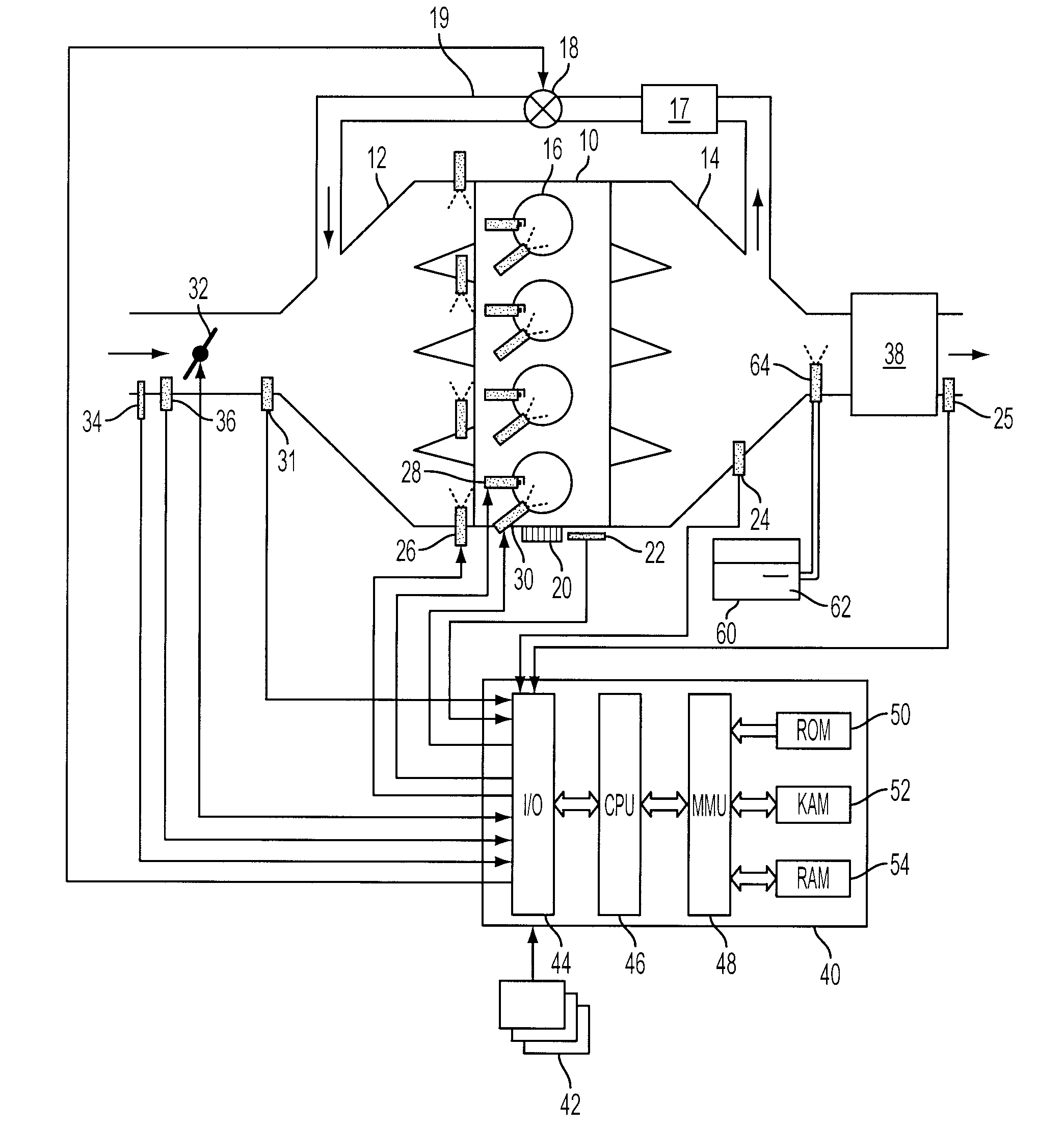
[0031] A four cylinder internal combustion engine 10 is shown by way of example in FIG. 1. Air is supplied to engine 10 through intake manifold 12 with spent gases discharged through exhaust manifold 14. An intake duct upstream of intake manifold 12 contains a throttle valve 32 which, when actuated, controls the amount of airflow to engine 10.

[0032] Two sensors 34 and 36 installed in in...


PUM

PropertyMeasurementUnit
porosityaaaaaaaaaa
porosityaaaaaaaaaa
porosityaaaaaaaaaa

Abstract

An emissions treatment device includes a substrate having multiple parallel channels / layers of a porous material, the channels / layers including a first group of channels / layers at least partially open along their length from an upstream end to a downstream end, and a second group of channels / layers that are at least partially open at the downstream end and may be substantially blocked at an upstream end, the parallel channels having complementary geometries and / or sizes. Coated metallic fibers or fleece facilitates flow of exhaust through walls of the first group into the second group of channels. Flow diverters or scoops may be formed in the walls between the first and second groups of channels to divert exhaust flow from the first group to the second group of channels. Catalyzed mesh sheets may be supported by perforated stainless steel sheets containing small passages and / or scoops to complement the useful wallflow by structure and flow design.

Description

CROSS-REFERENCE TO RELATED APPLICATION [0001] This application is a Continuation-In-Part of copending and commonly owned U.S. patent application Ser. No. 11 / 123,903 filed May 6, 2005.BACKGROUND [0002] 1. Technical Field [0003] The present disclosure relates to cell configurations for an exhaust treatment device for use with internal combustion engines. [0004] 2. Background Art [0005] Achieving low emissions, particularly low NOx (NO, nitric oxide, plus NO2, nitrogen dioxide) emissions from lean-burning engines, such as diesel engines is a challenge. SCRs (selective catalytic reductions)and LNTs (lean NOx traps) have been developed to treat NOx emitted from diesel engines. LNTs operate in a lean / rich cycle in which NOx is purged during lean operation and NOx is released and reacted in a shorter period of rich operation. A disadvantage of LNTs is that they significantly degrade diesel fuel economy. Although SCRs do not consume a large amount of extra fuel to react NOx, urea is supplie...

Claims


Application Information

Patent Timeline
Patent Type & Authority Applications(United States)
IPC IPC(8): B01D50/00
CPCF01N3/0222F01N3/206F01N3/208Y10T29/49345F01N2610/02F01N2610/146Y02T10/24F01N2560/021Y02T10/12F01N3/02
Inventor WILLEY, RAYZIMMERMAN, BRET A.KUBINSKI, DAVID J.BREHOB, DIANA D.
Owner FORD GLOBAL TECH LLC
Why Eureka
Try Eureka