
A Method of Directly Measuring Specimen Strain in Dielectric Environment

An environmental and direct technology, applied in the field of strain measurement, can solve the problems of complex fatigue deformation mechanism, no clear one-to-one correspondence of strain, plastic deformation, etc., and achieve the effect of direct measurement method, eliminating error and improving accuracy

Active Publication Date: 2018-04-20
CHINA INSTITUTE OF ATOMIC ENERGY
View PDF4 Cites 0 Cited by
  • Summary
  • Abstract
  • Description
  • Claims
  • Application Information

AI Technical Summary

Problems solved by technology

[0004] However, indirect methods have relatively large defects, because: the conversion formula is usually established through the test data in non-medium, when the formula is applied to high temperature, high pressure or other corrosive media, due to the state of the material itself and the stress state are affected Therefore, it will cause a large calculation error; the fatigue deformation mechanism is complex, not only elastic deformation but also plastic deformation in the deformation process of the sample, in addition, there is cyclic hardening / softening in the fatigue process; therefore, no matter the measured displacement value The measured strain of the "actual measurement part" has no clear one-to-one correspondence with the strain of the "required measurement part"

Method used


Image

  • A Method of Directly Measuring Specimen Strain in Dielectric Environment
  • A Method of Directly Measuring Specimen Strain in Dielectric Environment
  • A Method of Directly Measuring Specimen Strain in Dielectric Environment

Examples


Embodiment 1

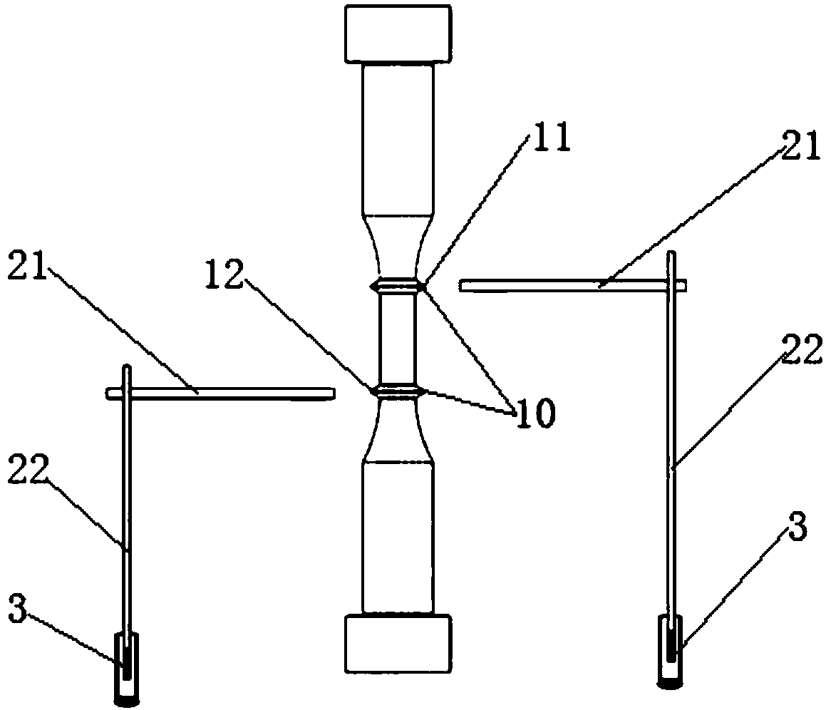
[0066] Like the sample strain direct measurement device described above, the difference of this embodiment is that the end of the guide 2 connected to the measuring part 3 is parallel to the axis of the sample 1, and the measuring part 2 measures the position of the end of the sample on the sample. 1 displacement in the axis direction.

[0067] In this way, the normal strain of the sample 1 to be measured can be measured.

[0068] In the process of practical application, the normal strain of the sample is generally much greater than its shear strain. In this case, because the normal strain is much greater than the shear strain, the influence of the shear strain generated during the measurement on the normal strain is very small and can be ignored. . In this case, the measurement method of this embodiment is preferred, only the displacement in the axial direction is measured, and then the strain value of the normal strain is calculated. In this way, the measurement process is...

Embodiment 2

[0070] Like the above-mentioned device for direct measurement of sample strain, the difference of this embodiment is that the measuring piece 3 is a displacement sensor, and the end of the guide 2 connected to the measuring piece 3 is inserted into the displacement sensor.

[0071] The displacement sensor is preferably an LVDT displacement sensor (Linear Variable Differential Transformer), which is an abbreviation of a linear variable differential transformer and belongs to a linear displacement sensor. The working principle is simply a movable iron core transformer. It consists of a primary coil, two secondary coils, iron core, coil bobbin, casing and other components. During the working process of the LVDT displacement sensor, the movement of the iron core cannot exceed the linear range of the coil, otherwise a nonlinear value will be generated, so all LVDT displacement sensors have a linear range.

[0072] In this way, the measurement of the displacement of the guide rod 2...

Embodiment 3

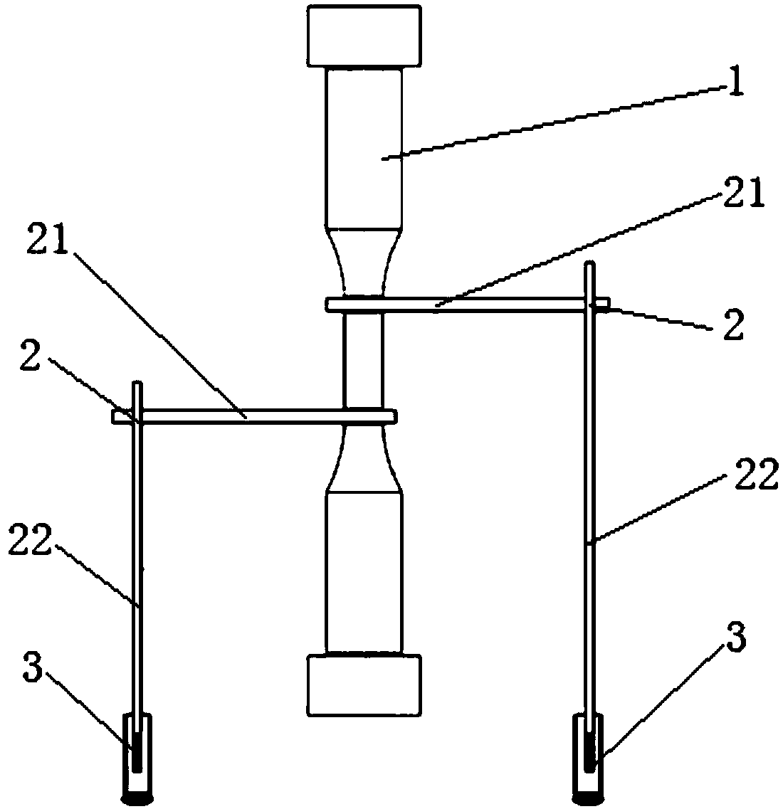
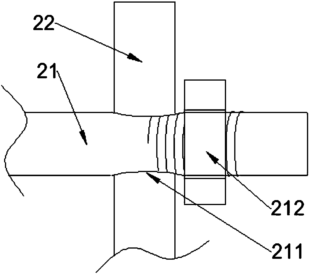
[0075] Like the above-mentioned direct measurement device for sample strain, the difference of this embodiment is that the guide 2 includes a guide fixture 21 and a guide rod 22; one end of the guide fixture 21 is clamped with the boss, and the other end is connected with the The guide rod 22 is fixedly connected; one end of the guide rod 22 is fixedly connected with the guide fixture 21, and the other end is inserted into the LVDT displacement sensor (measuring piece); the guide rod 22 is connected with the guide fixture 21 The position of the fixed connection is variable.

[0076] In this way, the position of the fixed connection between the guide rod 22 and the guide fixture 21 can be adjusted according to the actual installation position of the LVDT displacement sensor, thereby preventing the insertion end of the guide rod 22 from being inserted into the LVDT displacement sensor from exceeding the linear range of the LVDT displacement sensor, Causes the consequence that th...


PUM


Abstract

The invention provides a method for directly measuring specimen strain in a medium environment. The method comprises the following steps: a) carrying out redesign on a specimen; b) measuring the distance between two bosses, and fixedly arranging the specimen on a traction apparatus; c) clamping and fixing one end of each guidance clamp to the corresponding boss, and connecting the other end of the guidance clamp to a rigid guidance rod and enabling the guidance rod to be parallel to the specimen, and inserting each guidance rod into a displacement sensor, wherein the insertion portion is within the measurement range of the displacement sensor; d) placing the specimen in the medium environment, starting the traction apparatus to carry out traction on the specimen, recording the measurement values of the displacement sensors; and e) calculating the strain value of the specimen. Therefore, through the bosses, the part needing measuring can be measured directly; and compared with an indirect measurement method, the measurement method is more direct and higher in data measurement precision.

Description

technical field [0001] The invention relates to the technical field of strain measurement, in particular to a method for directly measuring sample strain in a medium environment. Background technique [0002] Nuclear power plant pressure vessels, primary circuit main pipes and other key components of reactors may fail due to corrosion fatigue when they work for a long time in the environment of high temperature and high pressure water medium and alternating loads. Therefore, it is necessary to carry out corrosion fatigue test research. The corrosion fatigue test requires the sample to carry out the strain control fatigue test in the corrosive medium, and the strain of the sample needs to be measured in real time. [0003] However, due to the high temperature, high pressure and corrosiveness of the corrosive medium, the conventional extensometer cannot be used to measure the strain of the sample, so the test is difficult. At present, the commonly used methods are as follows:...

Claims


Application Information

Patent Timeline
Patent Type & Authority Patents(China)
IPC IPC(8): G01B21/32
CPCG01B21/32
Inventor 钟巍华佟振峰宁广胜鱼滨涛
Owner CHINA INSTITUTE OF ATOMIC ENERGY
Learn More