
Method for real-time detection of diffraction phase of structure light field

A real-time detection and structured light technology, which is applied in the field of wavefront phase measurement of diffracted light field, can solve the problems of high difficulty, large amount of calculation, and low precision

Inactive Publication Date: 2016-06-15
UNIV OF SCI & TECH OF CHINA
View PDF3 Cites 28 Cited by
  • Summary
  • Abstract
  • Description
  • Claims
  • Application Information

AI Technical Summary

Problems solved by technology

Although the spatial phase shift can be measured dynamically, due to the different spatial positions of the interferogram records, different detectors are required (if multiple detectors are used to receive different phase shift interferograms) or different parts of the detectors (if a single detector is used to receive different phase shifts). Partially receive different phase-shifted interferograms) with consistent photoelectric performance, and pixel-level position matching and grayscale correction are required between interferograms at different spatial positions, the process is cumbersome and involves a large amount of calculation
Therefore, the actual operation process is difficult and high-precision, and it is difficult to be practically applied.
In addition, both the traditional time phase shift method and the space phase shift method need to be carried out under high vibration isolation conditions.

Method used


Image

  • Method for real-time detection of diffraction phase of structure light field
  • Method for real-time detection of diffraction phase of structure light field
  • Method for real-time detection of diffraction phase of structure light field

Examples


Embodiment Construction

[0034] The technical solutions in the embodiments of the present invention will be clearly and completely described below in conjunction with the accompanying drawings in the embodiments of the present invention. Obviously, the described embodiments are only some of the embodiments of the present invention, not all of them. Based on the embodiments of the present invention, all other embodiments obtained by persons of ordinary skill in the art without making creative efforts belong to the protection scope of the present invention.

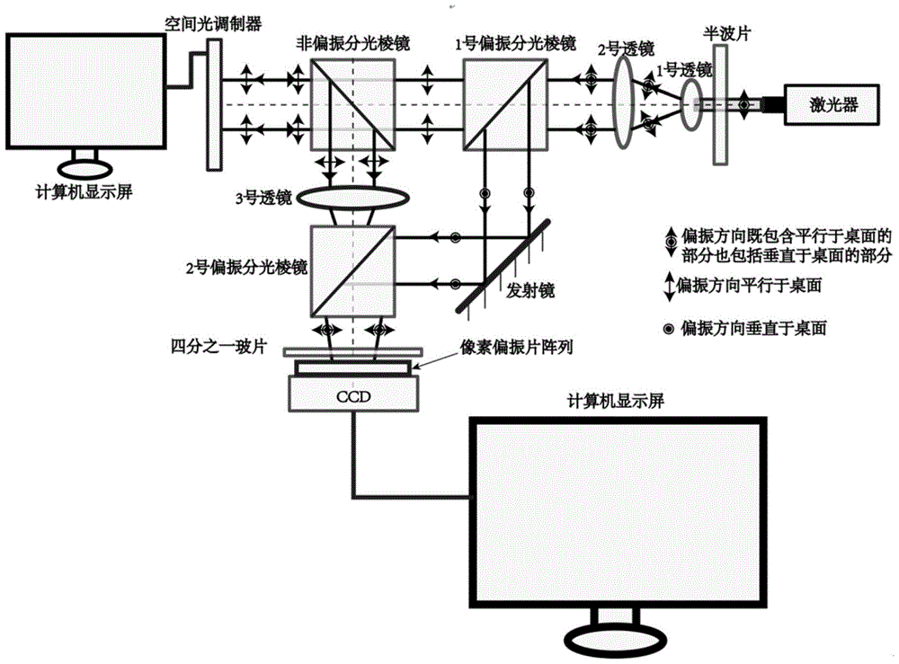
[0035] Embodiments of the present invention provide a real-time detection method for structured light field diffraction phase, which mainly includes the following steps:

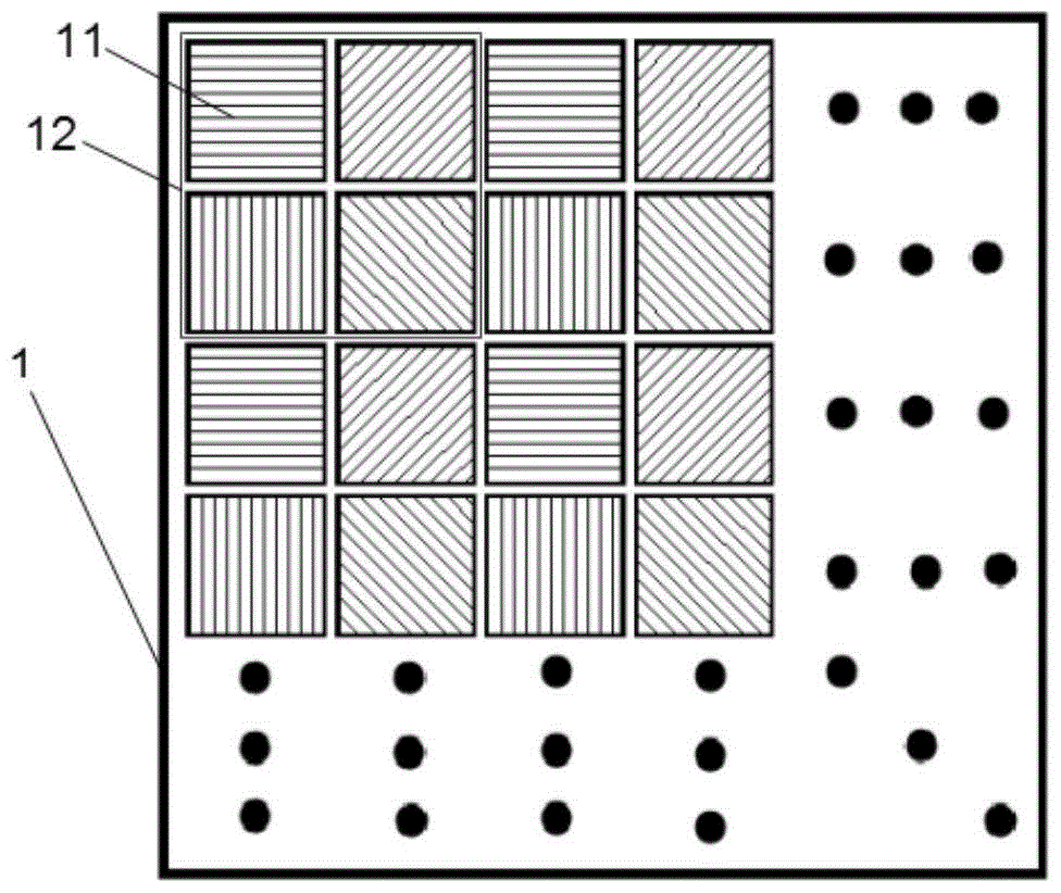
[0036] A camera integrated with a pixel polarizer array is used to collect the fringe pattern generated by the interference of the structured light output through the preset optical path and the reference light; wherein, the size of each polarizer unit in the pixel polarizer array...


PUM


Abstract

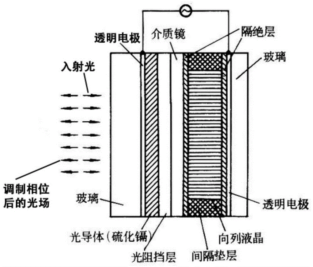
The invention discloses a method for real-time detection of the diffraction phase of a structure light field. The method includes the steps of: utilizing a camera integrated with a pixel polarizing film array to collect fringe patterns generated by interference of reference light beam output through a preset optical path and structured light beam generated by adjustment of a spatial light modulator, the dimensions of each polarizing film unit in the pixel polarizing film array and pixel dimensions of a photosensitive element in the camera being consistent and in one-to-one alignment; and extracting four fringe patterns of different polarization directions from the fringe patterns generated by interference of the structured light and the reference light according to the polarization directions of the polarizing film units so as to calculate the diffraction phase of the structure light field. The method disclosed by the invention realizes real-time measurement of light intensity and phase information of the structure light field, enables a user to deeply know physical characteristics of the structure light field, and has a very large driving function for the structure light field in the fields of optical tweezers, laser micromachining and optical signal propagation.

Description

technical field [0001] The invention relates to the field of wavefront phase measurement of a diffraction light field, in particular to a real-time detection method for the diffraction phase of a structured light field. Background technique [0002] Traditional single-frame camera equipment can only record the light intensity information of the light field by diffracting the plane, but cannot obtain the phase information of the light field. In order to record the phase information of the diffracted light field, the phase shifting technology is used to introduce the reference light, and the light intensity information of the multi-frame interferogram is recorded respectively by performing multiple phase shifts on the reference light, so as to calculate the light intensity and the recorded plane object light wave. phase information. [0003] Traditional phase shifting methods include time phase shifting and spatial phase shifting. Time phase shifting methods include piezoele...

Claims


Application Information

Patent Timeline
IPC IPC(8): G01J9/02G01J1/42
CPCG01J1/42G01J9/02G01J2001/4242G01J2009/0265
Inventor 张青川张云天马宣伍小平
Owner UNIV OF SCI & TECH OF CHINA
Learn More