Wire harness fatigue testing device and testing method

A technology of fatigue testing and testing methods, which is applied in the direction of measuring devices, using repeated force/pulsation force to test the strength of materials, instruments, etc., can solve the problems of poor test consistency and low test accuracy, and achieve good practicability and high test efficiency , Test consistency and high test accuracy

Active Publication Date: 2016-06-15
宁波拓普电器有限公司
View PDF6 Cites 11 Cited by
  • Summary
  • Abstract
  • Description
  • Claims
  • Application Information

AI Technical Summary

Problems solved by technology

[0005] The purpose of the invention of the present invention is to overcome the disadvantages of poor test consistency and low test accuracy of the wire harness fatigue test device in the prior art, and provide a wire harness fatigue test device and test device with high test efficiency, good test consistency and high test accuracy. method

Method used


Image

  • Wire harness fatigue testing device and testing method
  • Wire harness fatigue testing device and testing method
  • Wire harness fatigue testing device and testing method

Examples


Embodiment 1

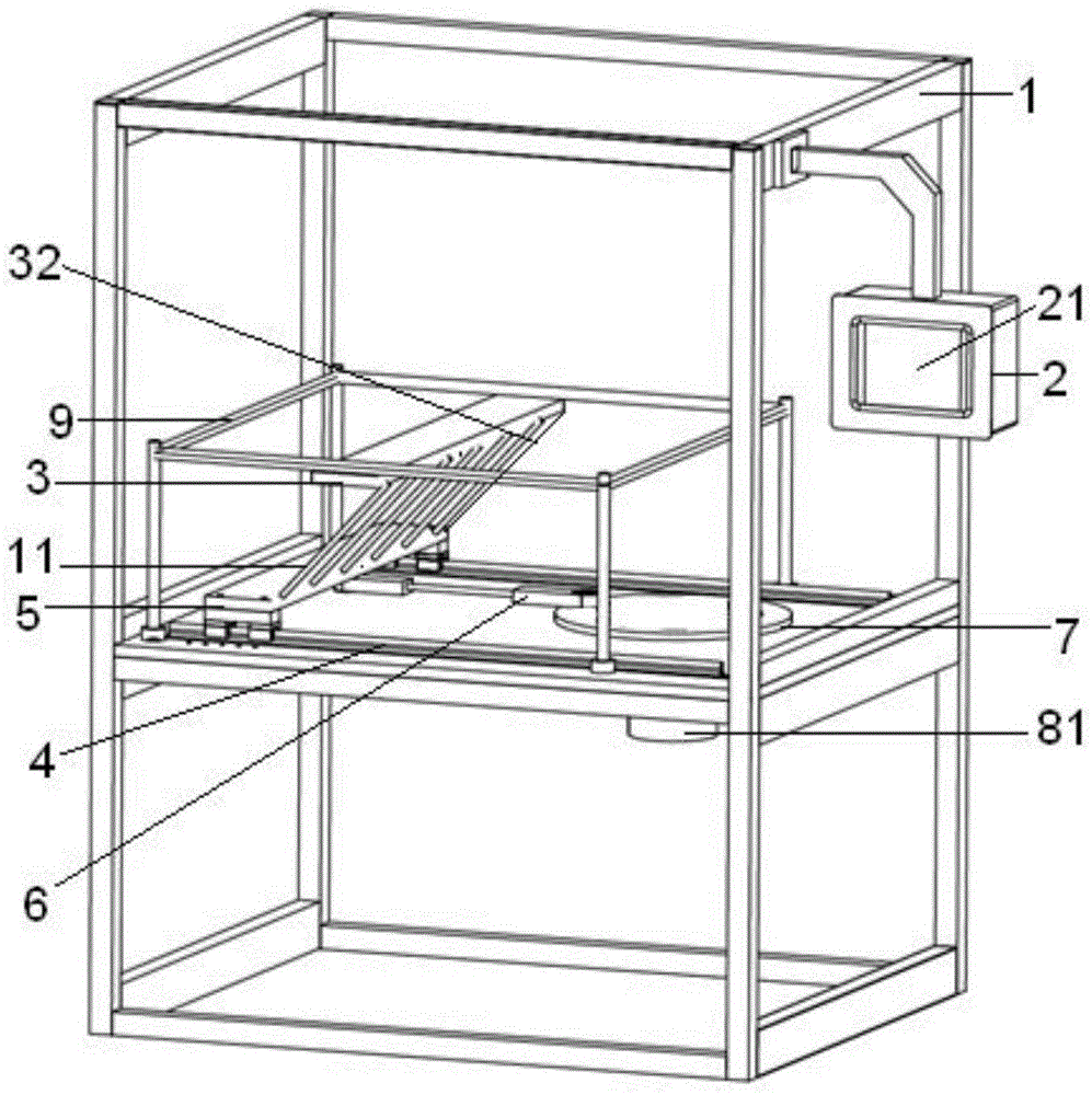
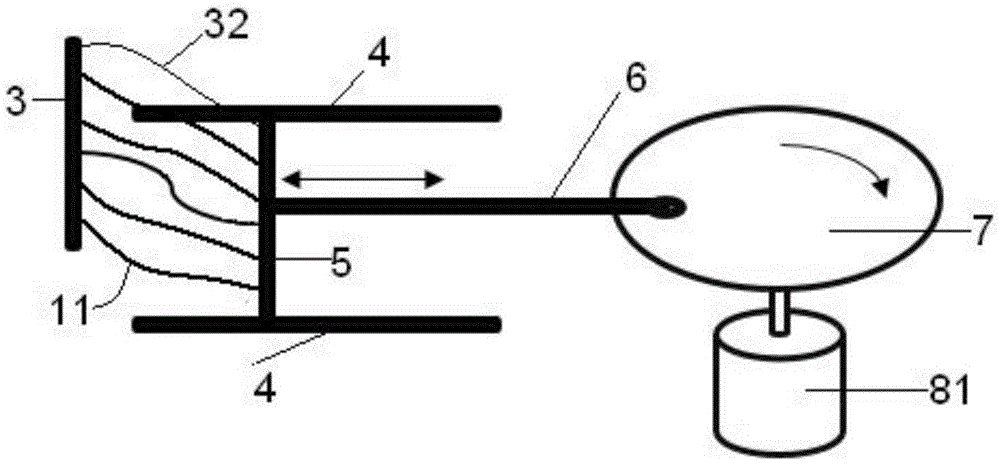
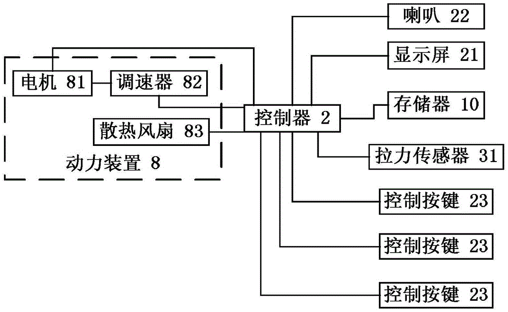
[0043] Such as figure 1 , figure 2The illustrated embodiment is a wire harness fatigue testing device, including a frame 1, a memory 10, a controller 2 arranged on the frame, a first wire harness fixing plate 3 extending longitudinally, and a 2 below the first wire harness fixing plate. A horizontal guide rail 4, a longitudinally extending second wire harness fixing plate 5 that is slidably connected to the two horizontal guide rails, a connecting rod 6, a horizontal turntable 7 located inside the two horizontal guide rails, and a power unit 8 connected to the horizontal turntable; one end of the connecting rod It is connected to one side of the second wiring harness fixing plate, and the other end of the connecting rod is connected to the edge of the horizontal turntable; the controller is provided with a display screen 21, a horn 22 and three control buttons 23. It also includes a horizontal rectangular frame 9 through which the first wire harness fixing plate is detachabl...

Embodiment 2

[0060] Embodiment 2 includes all structure and method parts of embodiment 1, such as figure 1 , image 3 As shown, the first wire harness fixing plate in embodiment 2 is provided with a tension sensor 31, and the tension sensor is connected to the second wire harness fixing plate through a test rope 32; the first wire harness fixing plate is detachably connected to the frame;

[0061] Step 90, debugging before testing

[0062] Step 901, the standard tension range is set in the memory; before pressing the start test button, the operator presses the debug button;

[0063] Step 902, the controller controls the horizontal turntable to rotate at a speed c through the power device, and the horizontal turntable drives the second wire harness fixing plate to reciprocate along the two horizontal guide rails through the connecting rod, and each of the first wire harness fixing plate and the second wire harness fixing plate A wire harness is stretched and bent repeatedly;

[0064] Ste...


PUM


Abstract

The invention discloses a wire harness fatigue testing device and a testing method. The device comprises a rack, a storage, a controller arranged on the rack, a first wire harness fixing plate longitudinally extending, two transverse guide rails positioned below the first wire harness fixing plate, a second wire harness fixing plate which longitudinally extends and is in sliding connection with the two transverse guide rails, a connecting rod, a horizontal turntable positioned inside the two transverse guide rails and a power device connected with the horizontal turntable; one end of the connecting rod is connected with one side of the second wire harness fixing plate; the other end of the connecting rod is connected with the part, close to the edge, of the horizontal turntable; the controller is provided with a display screen, a horn and a plurality of control keys; the controller is connected with the power device, the display screen, the horn, each control key and the storage electrically. The device has the characteristics of high testing efficiency, testing consistency and high testing precision.

Description

technical field [0001] The invention relates to the technical field of testing automotive electrical components, in particular to a wire harness fatigue testing device and testing method with high testing efficiency, good testing consistency and high testing precision. Background technique [0002] There are many wiring harnesses on the car, and the quality requirements for the wiring harnesses installed at two points with frequent changes in relative positions are higher. During the frequent and long-term work of the car, the wiring harness may be broken due to the aging of the wiring harness, causing safety hazards to the car . [0003] The wire harness fatigue testing device in the prior art has the disadvantages of low testing efficiency, poor testing consistency and low testing accuracy. [0004] Chinese Patent Authorization Publication No.: CN104374537A, the authorized publication date is February 25, 2015, which discloses an all-round wire harness fatigue test fixtur...

Claims


Application Information

Patent Timeline
Patent Type & Authority Applications(China)
IPC IPC(8): G01N3/38
CPCG01N3/38G01N2203/0005G01N2203/005G01N2203/0073
Inventor 叶志伟田刚徐政豪
Owner 宁波拓普电器有限公司
Why Eureka
Try Eureka