

Distributed direct current micro-grid control method and control system
A technology of DC micro-grid and control method, which is applied in the direction of parallel operation of DC power supplies, and can solve the problems of unsuitable application occasions where power station construction is inconvenient, and achieve the effects of convenient local control, high traffic speed, and high stability
- Summary
- Abstract
- Description
- Claims
- Application Information
AI Technical Summary
Problems solved by technology
Method used
Image

Examples
specific Embodiment 1
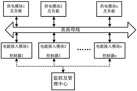
[0031] A distributed DC micro-grid control method, the specific control method is: setting the respective output level voltages of n power input modules capable of inputting electric energy to the DC bus; Compared with the voltage value, if the voltage value of the current DC bus is lower than the output level voltage of a certain power input module, the power input module will input electric energy to the DC bus with the maximum power it can output; if the current voltage of the DC bus is higher than output level voltage of a power input module, the power input module is prohibited from inputting power to the DC bus; if the current DC bus voltage is equal to the output level voltage of a certain power input module, the output power of the power input module is controlled so that Ensure that the voltage on the current DC bus is constant; the n is a natural number greater than or equal to 2.
[0032] A control system based on the above-mentioned distributed DC microgrid control...
specific Embodiment 2
[0037]On the basis of specific embodiment 1, the output level voltage is the output level voltage range including the error range; compare the output level voltage range of each power input module with the voltage value on the current DC bus, if the current DC bus If the voltage value is lower than the lower limit of the output level voltage error of a certain power input module, the power input module will input power to the DC bus with the maximum power it can output; if the current DC bus voltage value is higher than the output level voltage of a certain power input module If the upper limit of the error is set, the power input module is prohibited from inputting power to the DC bus; if the current voltage value of the DC bus is within the output level voltage error range of a certain power input module, the output power of the power input module is controlled to ensure that the current DC The voltage on the bus is constant; said n is a natural number greater than or equal t...
specific Embodiment 3
[0038] On the basis of specific embodiment 1 or 2, the output level voltage division principle includes: the output level voltage of the renewable energy power input module is higher than the output level voltage of the non-renewable energy power input module; The output level voltage is higher than the output level voltage of the energy storage connected electric energy input module.
[0039] For example: the current power input module includes solar power input module, wind power power input module, grid power power input module and battery power power input module; An output level voltage a (such as 620V), the power grid connected to the power input module corresponds to an output level voltage b (such as 610V), and the battery connected to the power input module corresponds to an output level voltage c (such as 600V), and a>b>c , then 4 power input modules correspond to 3 output level voltages. If the current DC bus voltage value is 610V, since it is lower than the output...
PUM
 Abstract
Description
Claims
Application Information