Synchronous triggering and monitoring method and device for asynchronous multiple sensors

A multi-sensor, synchronous triggering technology, applied to TV, color TV parts, electrical components, etc., can solve the problems of no trigger signal real-time feedback mechanism, failure to detect abnormalities in time, unclear sensor working conditions, etc.

Active Publication Date: 2016-06-15
纵横皆景(武汉)信息技术有限公司
View PDF11 Cites 2 Cited by
  • Summary
  • Abstract
  • Description
  • Claims
  • Application Information

AI Technical Summary

Problems solved by technology

[0003] In the solutions disclosed in the prior art, there is no real-time feedback mechanism after the trigger signal is sent out. Since the trigger sensor of the trigger board only includes the subjective control process, the operator does not know the working conditions of each sensor, and cannot detect abnormalities in time and take immediate remedies measure

Method used


Image

  • Synchronous triggering and monitoring method and device for asynchronous multiple sensors
  • Synchronous triggering and monitoring method and device for asynchronous multiple sensors
  • Synchronous triggering and monitoring method and device for asynchronous multiple sensors

Examples


Embodiment 1

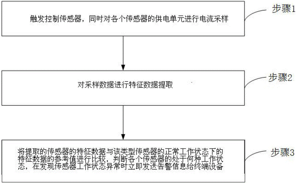
[0041] Such as figure 1 Shown is a flow chart of a method for asynchronous multi-sensor synchronous triggering and monitoring provided by the present invention, by figure 1 It can be seen that the method for asynchronous multi-sensor synchronous triggering and monitoring provided by the present invention, after sending a trigger signal to each sensor, includes:

[0042] Step 1, triggering the control sensor, and performing current sampling on the power supply unit of each sensor at the same time.

[0043] Step 2, extracting feature data from the sampled data.

[0044] Step 3, compare the extracted characteristic data of the sensor with the reference value of the characteristic data in the normal working state of this type of sensor, judge which working state each sensor is in, and send an alarm message to the Terminal Equipment.

[0045] An asynchronous multi-sensor synchronous triggering and monitoring method provided by the embodiment of the present invention, according t...

Embodiment 2

[0066] Embodiment 2 provided by the present invention is an embodiment of an asynchronous multi-sensor synchronous triggering and monitoring device provided by the present invention. In the embodiment of the present invention, the sensor is specifically a camera. After the synchronous trigger board of the multi-camera triggers the camera, the camera will The images are captured and uploaded in real time, but the on-site staff does not know the working status of the camera, and it is possible to continue working even when individual cameras are not working, resulting in a waste of time and labor. By obtaining the current data of the camera after the camera is triggered in real time, Comparing with the feature data of this type of camera in normal working state, the staff can know in real time whether each camera is in normal working state, so that when some cameras are not working, they can know in time and perform real-time processing.

[0067] Further, in an embodiment of the ...

Embodiment 3

[0074] Embodiment 3 provided by the present invention is an embodiment of an asynchronous multi-sensor synchronous triggering and monitoring device provided by the present invention. The device includes a current sampling unit connected to a central control unit and a sensor power supply unit respectively.

[0075] The device sends commands to control the sensor to work, and the current sampling unit collects the working current data of the sensor power supply unit in real time.

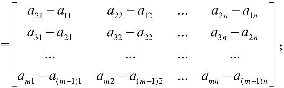
[0076] The central control unit extracts the characteristic data of the working current data, compares the characteristic data with the characteristic data in the normal working state of the sensor, and judges which working state the sensor is in. The characteristic data is the integral of the sampled current data and the differential square sum

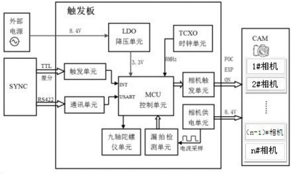
[0077] The sensor can be a camera such as figure 2 Shown is a schematic structural diagram of a multi-camera synchronous triggering device provided b...


PUM


Abstract

The invention is applicable to the field of sensor monitoring, and provides a synchronous triggering and monitoring method and device for asynchronous multiple sensors. The method comprises the following steps: performing real-time synchronous and independent current sampling on a power supply unit of each sensor; performing characteristic data extraction on sampled data; and comparing extracted characteristic data with reference values of characteristic data of the sensor of this type under each working state, and judging the working state of the characteristic data. Current data of the sensor after triggering the sensor are acquired in real time, and then staff can know the working state of each sensor in real time, and process sensors under abnormal working states in real time, so that the synchronous triggering and monitoring method and device for the asynchronous multiple sensors provided by the invention are especially suitable for real-time monitoring of sensors used in the fields of mobile measurement and high-risk road sections which need to be processed timely.

Description

technical field [0001] The invention belongs to the field of electrical equipment monitoring, in particular to a method and device for synchronous triggering and monitoring of asynchronous multi-sensors. Background technique [0002] In the prior art, there is a lack of technology for monitoring the working status after the sensor is triggered. Take the multi-camera synchronization trigger board as an example. In the technical solution disclosed in the Chinese invention patent of "triggering device, multi-camera synchronous photographing system, multi-camera synchronous photographing method (application number: 201410427752.6)", through external control, multiple cameras connected to the device can simultaneously focus and photograph , Using optocoupler isolation technology, so that each camera does not interfere with each other and works independently. The optocoupler is not a mechanical structure, and its life is longer than that of a relay, reducing the probability of dam...

Claims


Application Information

Patent Timeline
Patent Type & Authority Applications(China)
IPC IPC(8): H04N5/232H04N5/247
CPCH04N23/66H04N23/65H04N23/90
Inventor 王刚薛利荣
Owner 纵横皆景(武汉)信息技术有限公司
Why Eureka
Try Eureka