A flue gas desulphurization denitration method adopting ammonia-containing wastewater for flue gas temperature control and a device therefor

A technology for flue gas and wastewater, applied in separation methods, chemical instruments and methods, air quality improvement, etc., can solve problems such as increasing operating costs and increasing ammonia consumption

Active Publication Date: 2016-06-22
HUNAN ZHONGYE CHANGTIAN ENERGY CONSERVATION & ENVIRONMENTAL PROTECTION TECH CO LTD
View PDF14 Cites 11 Cited by
  • Summary
  • Abstract
  • Description
  • Claims
  • Application Information

AI Technical Summary

Problems solved by technology

In addition, SO in flue gas 3 , HF, and HCl will also react with NH 3 reaction, for denitrifica...

Method used


Image

  • A flue gas desulphurization denitration method adopting ammonia-containing wastewater for flue gas temperature control and a device therefor
  • A flue gas desulphurization denitration method adopting ammonia-containing wastewater for flue gas temperature control and a device therefor
  • A flue gas desulphurization denitration method adopting ammonia-containing wastewater for flue gas temperature control and a device therefor

Examples


specific Embodiment approach

[0118] The mixing device (M) used in the following examples includes an air pipeline (602), an ammonia pipeline (606), an air helical section (609), an ammonia helical section (610), a mixing section (612) and a mixing Gas outlet (616), wherein the ammonia pipe (606) is inserted (or extended into) the air pipe from one side of the larger diameter air pipe (602), then bent and along the axis of the air pipe (602) along the The air flow direction extends a certain distance L (it is for example 20-80%, more preferably 35-65% of the total length of the mixing device, such as L=0.2-2 meters, preferably 0.3-1.5 meters), the end of the ammonia pipeline (606) The section is an ammonia gas spiral segment (610), and the ammonia gas spiral segment (610) includes m helical ammonia passages separated by m longitudinally extending spiral plates (608) in the ammonia pipeline (606), in addition , the air spiral section (609) corresponding to the ammonia gas spiral section (610) comprises a sp...

Embodiment approach 1

[0129] use Figure 2A , 2B and the flowsheet and adsorption column shown in 2C.

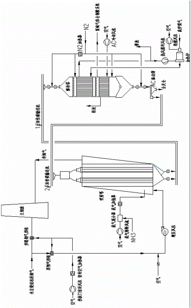
[0130] Activated carbon adsorption tower device includes

[0131] 1) adsorption tower (1),

[0132] 2) The raw flue gas conveying flue (102) upstream of the flue gas input port of the adsorption tower, wherein a cold air inlet is provided on the upstream position P1 of the flue, and a process water nozzle is provided on the downstream position P2 of the flue (P2),

[0133] 3) An optional (ie optional) air cooler (509) connected to the cold air inlet at position P1,

[0134] 4) The process water delivery pipeline (508) connected with the process water nozzle (P2) on the P2 position, a branch is branched from the pipeline 508 and connected to the ammonia-containing waste water storage tank in the acid production area, so as to be transported from the storage tank Ammonia-containing waste water to process water nozzle (P2),

[0135] 5) A booster fan (514) located between the P1 and P2 position...

Embodiment approach 2

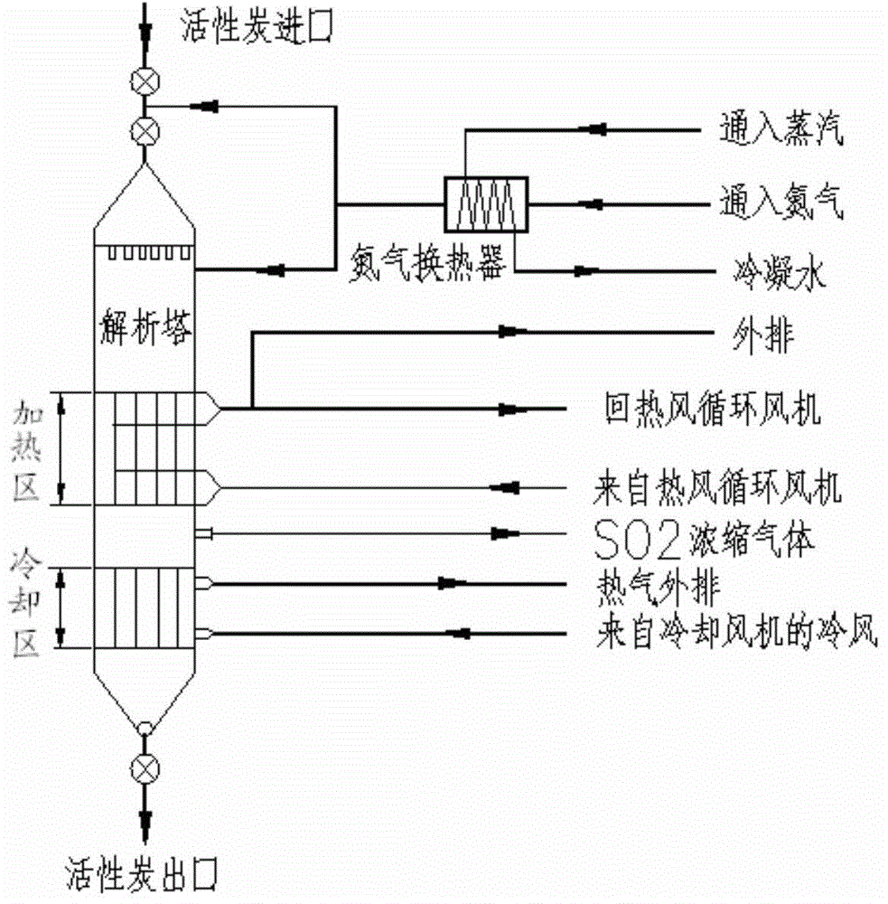
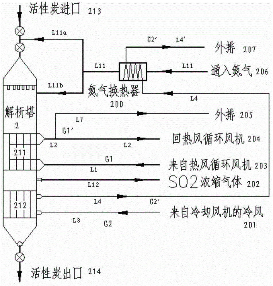
[0161]Repeat embodiment 1, only: a part (such as 4-25vol%, preferably 6-20vol%, more preferably 8-15vol%) of the above-mentioned externally exhausted hot air (G1 ') is delivered to the nitrogen heat exchanger (100) and nitrogen Indirect heat exchange is performed to heat the nitrogen, and the nitrogen is heated to 105-155°C (preferably 110-150°C, more preferably 115-140°C). Then, the cool air (G2') subjected to heat exchange is discharged. And, likewise, the ammonia-containing waste water produced in the acid production zone replaces the above-mentioned process water or replaces a part of the above-mentioned process water.


PUM


Abstract

A flue gas desulphurization denitration method adopting ammonia-containing wastewater for flue gas temperature control and a device therefor are provided. The method includes I) a step of flue gas temperature control and II) a step of desulphurization and denitration, wherein the step of flue gas temperature control comprises (1) a step of subjecting flue gas to first time of cooling by feeding cold air into a flue conveying high-temperature flue gas to an activated-carbon adsorption column from a cold-air inlet at an upstream position (P1) of the flue, and (2) spraying the ammonia-containing wastewater into the flue gas in the flue from a process water spray nozzle at the downstream position (P2) of the position (P1) from which the cold air is fed, adjusting the temperature of the flue gas fed into the adsorption column to be in a preset range of T3, for example, the T3 ranges from 100-150 DEG C. The temperature of the flue gas fed into the adsorption column is controlled by mixing with the cold air and spraying water.

Description

technical field [0001] The invention relates to a flue gas desulfurization and denitrification method and device for using ammonia-containing waste water in flue gas temperature control. More specifically, the present invention relates to the measures of cooling the flue gas (sintering flue gas) at the upstream or front end of the activated carbon adsorption tower by spraying water and adding cold air to control the temperature of the flue gas entering the adsorption tower at 100-150°C range, preferably controlled within the range of 120 ~ 140 ° C, these belong to the field of sintering flue gas treatment. Background technique [0002] For industrial flue gas, especially sintering machine flue gas in the iron and steel industry, it is ideal to use large-scale dry desulfurization and denitrification devices and processes including activated carbon adsorption towers and desorption towers. Activated carbon flue gas purification technology has the characteristics of simultaneou...

Claims


Application Information

Patent Timeline
IPC IPC(8): B01D53/76B01D53/60B01D53/02
CPCY02A50/20
Inventor 刘旭华叶恒棣李勇刘昌齐钮心洁陈红颜学宏黄伏根魏进超张震
Owner HUNAN ZHONGYE CHANGTIAN ENERGY CONSERVATION & ENVIRONMENTAL PROTECTION TECH CO LTD
Why Eureka
Try Eureka