Test tube rack easy to dry and discharge inside-tube water
A technology of test tubes and intermediate plates, applied in the direction of test tube holders/clamps, drying, dryers, etc., can solve the problems of liquid overflow on the test bench, etc., and achieve the effects of saving space on the test bench, easy operation, and simple structure
- Summary
- Abstract
- Description
- Claims
- Application Information
AI Technical Summary
Problems solved by technology
Method used
Image

Examples
Embodiment 1
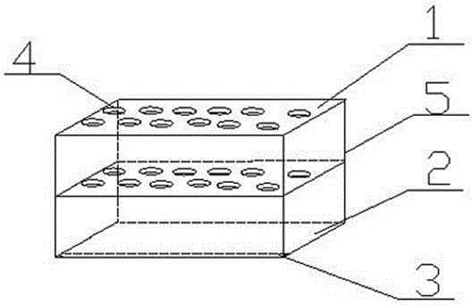
[0025] Such as figure 1 , figure 2 , image 3 As shown, a device rack for conveniently discharging and drying test tube water includes a top plate 1, a bottom plate 2, and a middle plate. The top plate 1, the middle plate, and the bottom plate 2 are arranged in layers from top to bottom. The bottom plate 2 is provided with through holes 4 , and the upper surface of the bottom plate 2 is sunken downward to form a water storage tank 3 .
[0026] In this embodiment, by setting the water storage tank 3 around the upper surface of the bottom plate 2 of the test tube rack, when the test tube passes through the through hole 4 and is placed upside down on the test tube rack, the liquid flowing out from the test tube gathers in the water storage tank 3 to prevent It overflows to the test bench, and when the water in the accumulation tank 3 gathers more, it will be processed together, and the test tube water will be dried in time to be discharged.
[0027] In this embodiment, the ma...
Embodiment 2
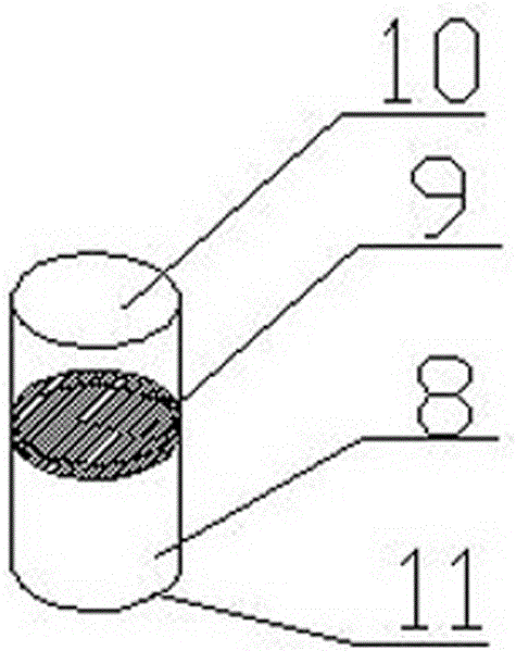
[0029] This embodiment is further limited on the basis of the above-mentioned embodiments, the four corners of the top plate 1, the middle plate, and the bottom plate 2 are all provided with connecting portions 8, between the connecting portion 8 of the top plate 1 and the connecting portion 8 of the middle plate, the middle plate The connection part 8 of the bottom plate 2 is connected by the connection rod 5; the connection part 8 is a cylindrical cavity, and the middle part of the connection part 8 is provided with a partition 9. Here, the connection mode between the top plate 1 and the middle plate, between the middle plates, and between the middle plate and the bottom plate 2 is specifically limited, and the connection mode of thread adaptation is used to improve the stability of the test tube rack, and at the same time it is convenient for the test tube rack. for assembly and disassembly.
[0030] In this embodiment, the top plate 1 and the middle plate are cuboid plates...
Embodiment 3
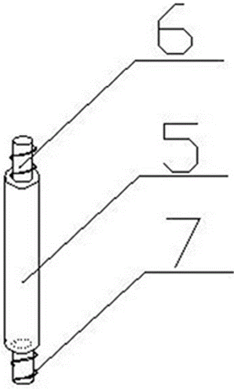
[0033] In this embodiment, on the basis of the above embodiments, it is further defined that the two ends of the partition 9 are respectively the first cavity 10 and the second cavity 11, and both the first cavity 10 and the second cavity 11 are provided with Internal threads, the two ends of the connecting rod 5 are respectively provided with a first cylindrical rod 6 and a second cylindrical rod 7, and the first cylindrical rod 6 and the second cylindrical rod 7 are both provided with external threads. Here, the connection mode between the top plate 1 and the middle plate, between the middle plates, and between the middle plate and the bottom plate 2 is specifically limited, and the connection mode of thread adaptation is used to improve the stability of the test tube rack and facilitate the adjustment of the entire test tube rack. assembly and disassembly. Other structures involved in this embodiment are the same as those in the foregoing embodiments, and will not be repeat...
PUM
 Abstract
Description
Claims
Application Information
 - R&D
- Intellectual Property
- Life Sciences
- Materials
- Tech Scout
- Unparalleled Data Quality
- Higher Quality Content
- 60% Fewer Hallucinations
Browse by: Latest US Patents, China's latest patents, Technical Efficacy Thesaurus, Application Domain, Technology Topic, Popular Technical Reports.
© 2025 PatSnap. All rights reserved.Legal|Privacy policy|Modern Slavery Act Transparency Statement|Sitemap|About US| Contact US: help@patsnap.com