Cleaning machine for gas spring pressure pipe

A pressure tube and cleaning machine technology, applied in the field of gas spring manufacturing, can solve the problems of poor cleaning quality of pressure tubes, achieve the effects of increasing cleaning effect, high cleaning efficiency, and increasing pressing force

Inactive Publication Date: 2016-06-22
CHANGZHOU GAS SPRING
View PDF8 Cites 8 Cited by
  • Summary
  • Abstract
  • Description
  • Claims
  • Application Information

AI Technical Summary

Problems solved by technology

[0003] The technical problem to be solved by the present invention is: in order to solve the problem of poor cleaning quality of pressure pipes in the prior art, a cleaning machine for pressure pipes of gas springs is now provided

Method used


Image

  • Cleaning machine for gas spring pressure pipe
  • Cleaning machine for gas spring pressure pipe
  • Cleaning machine for gas spring pressure pipe

Examples


Embodiment 1

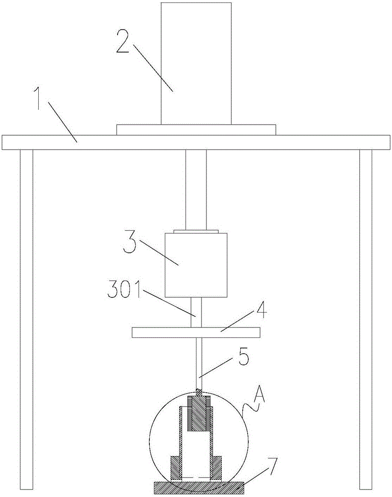
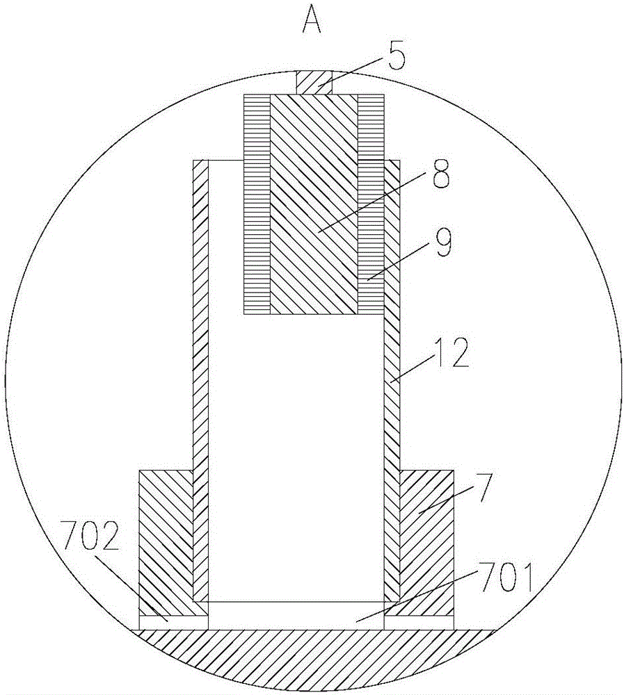
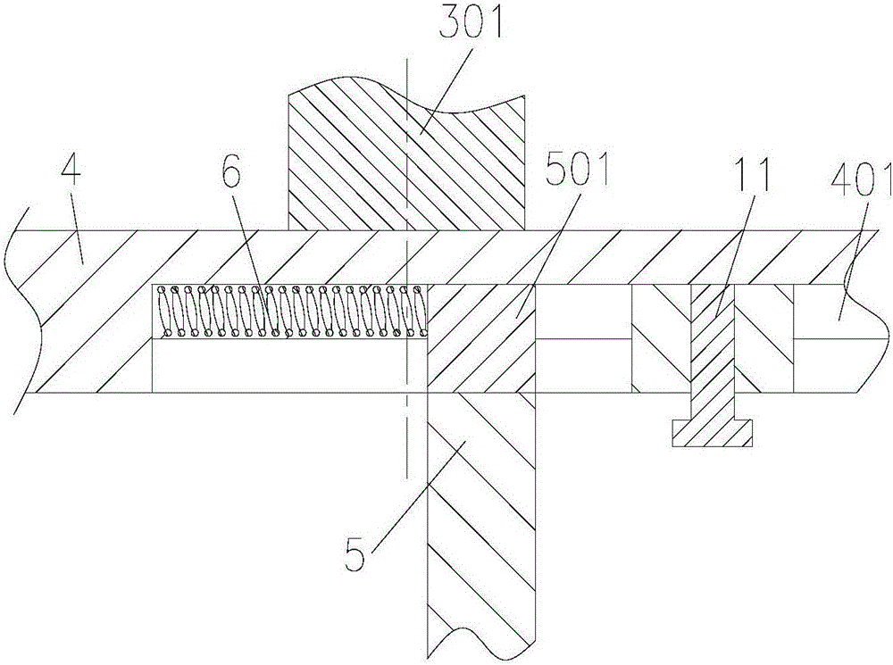
[0017] Such as Figure 1-3 As shown, a cleaning machine for a gas spring pressure tube includes a frame 1 and a hydraulic cylinder 2 arranged on the frame 1 with an extended end facing downward, and a motor 3 is arranged on the extended end of the hydraulic cylinder 2 A turntable 4 is fixedly connected to the main shaft 301 of the motor 3, the turntable 4 is provided with a rotating shaft 5, the upper end of the rotating shaft 5 is provided with a T-shaped protrusion 501, and the lower end of the rotating shaft 5 is provided with a brush assembly, so The lower surface of the turntable 4 is provided with a T-shaped groove 401 that matches the T-shaped protrusion 501, the T-shaped protrusion 501 is slidably arranged in the T-shaped groove 401, and the T-shaped groove 401 is connected to the T-shaped groove 401. A spring 6 is arranged between the T-shaped protrusions 501, and a fixing seat 7 is arranged below the brush assembly. The fixing seat 7 is provided with a positioning hol...


PUM


Abstract

The invention relates to the technical field of gas spring manufacturing, in particular to a cleaning machine for a gas spring pressure pipe. The cleaning machine comprises a rack and a hydraulic cylinder arranged on the rack, and the extending end of the hydraulic cylinder faces downwards. A motor is arranged at the extending end of the hydraulic cylinder. A rotary plate is fixedly connected to a main shaft of the motor. A rotary shaft is arranged on the rotary plate. A T-shaped protrusion is arranged at the upper end of the rotary shaft. A bristle brush assembly is arranged at the lower end of the rotary shaft. A T-shaped groove matched with the T-shaped protrusion is formed in the lower surface of the rotary plate. A spring is arranged between the T-shaped groove and the T-shaped protrusion. A fixing base is arranged under the bristle brush assembly. A positioning hole matched with the pressure pipe is formed in the fixing base. The positioning hole and the rotary plate are coaxial. The bristle brush assembly is placed in the positioning hole by transversely moving the rotary shaft, the spring is in a compressed state at the moment, and one side of the bristle brush assembly is tightly attached to the inner wall of the pressure pipe under the action of the spring so that the inner wall of the pressure pipe can be better cleaned by the bristle brush assembly. The cleaning effect on the pressure pipe is improved, and the cleaning efficiency is high.

Description

Technical field [0001] The invention relates to the technical field of gas spring manufacturing, in particular to a cleaning machine for gas spring pressure tubes. Background technique [0002] Gas spring is a component that requires high precision and cleanliness. As the main body of the gas spring component, the pressure tube requires a roughness of Ra0.2 on the outer and inner walls. Because the core rod lubricating grease sticks to the inner wall during the cold drawing of the tube material In addition, in machining and cutting, a lot of iron filings will stick into the inner wall of the hole, so cleaning the inner wall of the pressure tube becomes a necessary process before the next process. The conventional cleaning of the pressure tube is manual. One hand puts the pressure tube into the kerosene, and the other hand holds the brush corresponding to the inner diameter and length of the pressure tube to reciprocate in the hole. The tube continuously rotates to clean the inne...

Claims


Application Information

Patent Timeline
Patent Type & Authority Applications(China)
IPC IPC(8): B08B9/045
CPCB08B9/045B08B9/0433B08B2209/04
Inventor 岳彩莲施云宵杨峰
Owner CHANGZHOU GAS SPRING
Why Eureka
Try Eureka