Tire grinding device

A tire and grinding mechanism technology, applied in grinding machines, grinding workpiece supports, grinding/polishing equipment, etc., can solve problems such as depressions, and achieve the effects of increased strength, stable positioning, and simple structure

Inactive Publication Date: 2016-06-22
HUAIYIN INSTITUTE OF TECHNOLOGY
View PDF9 Cites 11 Cited by
  • Summary
  • Abstract
  • Description
  • Claims
  • Application Information

AI Technical Summary

Problems solved by technology

The situation that can be encountered in the above process is: the tire is fixed or positioned near the grinding wheel, preferably after the tire is fixed, the tire can be rotated along its axis to grind the circumferential surface of the tire; at the same time, the proble

Method used


Image

  • Tire grinding device
  • Tire grinding device
  • Tire grinding device

Examples


Embodiment Construction

[0027] The present invention will now be further described in detail in conjunction with the accompanying drawings and embodiments. These drawings are all simplified schematic diagrams, only illustrating the basic structure of the present invention in a schematic manner, so it only shows the composition related to the present invention.

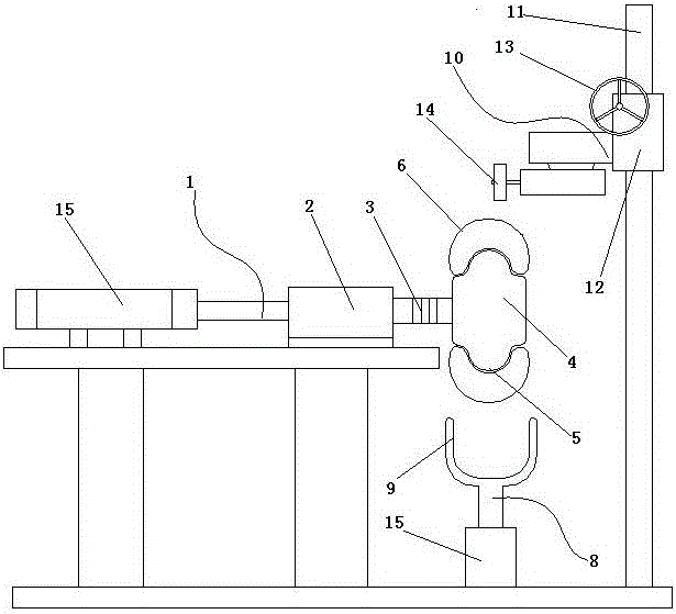
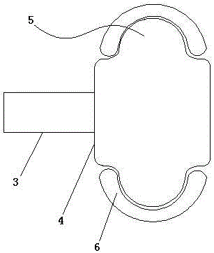
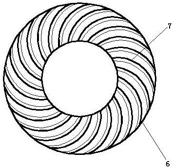
[0028] like Figure 1-4 As shown, a kind of tire grinding device comprises: positioning mechanism 1 with positioning head 2, feeding mechanism 8 located below positioning head 2, and grinding mechanism 10 close to positioning head 2, positioning head 2 is provided with rotating shaft 3, rotating shaft 3. A runner 4 with a bulge 5 is arranged at the end, and an annular airbag 6 is sheathed on the periphery of the runner 4. A groove matching the structure of the bulge 5 is arranged on the inner periphery of the annular airbag 6. The structure of the bulge 5 is consistent with that of the airbag. The groove structures on the inner periphery of t...


PUM


Abstract

The invention relates to a tire grinding device. The tire grinding device comprises a positioning mechanism with a positioning head, and a grinding mechanism close to the positioning head. The positioning head is provided with a rotating shaft. A runner is arranged at the end of the rotating shaft. Protruding parts are arranged on the runner in the outer circumferential direction. The outer circumference of the runner is sleeved with an annular air bag. Grooves coinciding with the structures of the protruding parts are formed in the inner circumference of the annular air bag. The air bag is provided with an air nozzle. Protruding patterns are arranged on the outer surface of the air bag, incline by a certain angle in the radial direction of the annular new air bag and extend. The grinding mechanism is arranged on a vertical guide rod, a grinding wheel is further arranged on the grinding mechanism, and the positioning head can be close to the grinding wheel under driving of the drive mechanism. By means of the air bag, a positioning mechanism made of metal or other hard materials is replaced in the prior art, the positioning mechanism conducts full-area fixing on a tire in an inner cavity of the tire, and after the air bag is fully inflated with air, the inner cavity of the tire can be inflated fully through the air bag, and the inner portion of the tire is supported; and during grinding wheel grinding, the grinding position is not prone to being sunk.

Description

technical field [0001] The invention relates to a grinding device, in particular to a tire grinding device. Background technique [0002] During the tire grinding process, two situations are involved. One is tire retreading, by grinding the tire surface clean, removing oil stains, damaged parts, etc.; the other is grinding some corners and excess parts of new tires, and grinding the new stubble after cutting. The situation that can be encountered in the above process is: the tire is fixed or positioned near the grinding wheel, preferably after the tire is fixed, the tire can be rotated along its axis to grind the circumferential surface of the tire; at the same time, the problem often encountered is, Because the tire has an inner cavity, when grinding, the position where the tire is ground is often easily depressed by the emery wheel, and the tire is pressed by the emery wheel, so the emery wheel is difficult to grind well here. Contents of the invention [0003] The inv...

Claims


Application Information

Patent Timeline
IPC IPC(8): B24B5/36B24B41/00B24B41/06
CPCB24B5/366B24B41/00B24B41/067
Inventor 汪通悦蒋志鹏许兆美洪宗海
Owner HUAIYIN INSTITUTE OF TECHNOLOGY
Why Eureka
Try Eureka