Mold locking oil cylinder structure

A technology of clamping oil cylinder and oil channel, which is applied in the field of mold clamping cylinder structure, can solve the problems of increased energy consumption, slow hydraulic oil circulation speed, low oil flow, etc., achieve reliable and accurate work, increase work reliability, and improve The effect of cycle efficiency

Inactive Publication Date: 2016-06-22
GUANGDONG BLOOMACHINE
View PDF2 Cites 0 Cited by
  • Summary
  • Abstract
  • Description
  • Claims
  • Application Information

AI Technical Summary

Problems solved by technology

[0002] Most of the traditional clamping cylinders adopt the external circulation type clamping cylinder, that is, the hydraulic oil of the cylinder in the clamping cylinder needs to be connected from the outside and circulate with the outside world. The structure of the traditional clamping cylinder is relatively complicated. Its cycle needs to set multiple oil inlet and outlet holes on the cylinder, but the hydraulic oil circulation speed in the clamping cylinde...

Method used


Image

  • Mold locking oil cylinder structure
  • Mold locking oil cylinder structure

Examples


Embodiment Construction

[0014] The present invention will be described in further detail below in conjunction with the accompanying drawings.

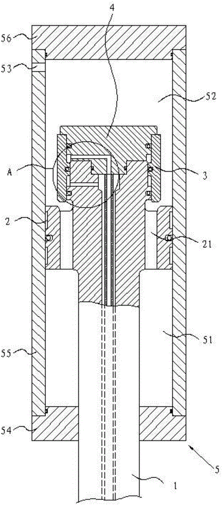
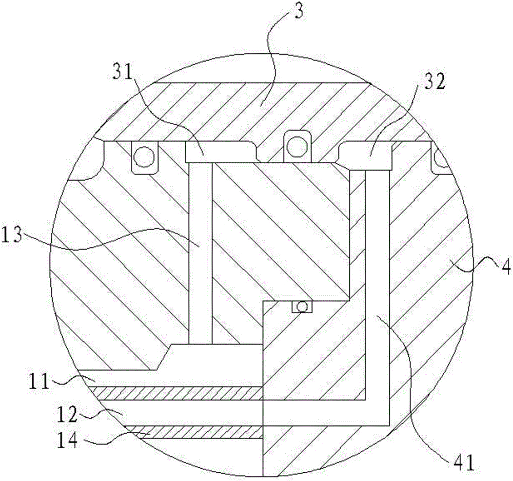
[0015] refer to figure 1 with figure 2 , a clamping cylinder structure of the present invention, including a piston rod 1, a piston 2, a valve core 3, a valve cover 4, and a cylinder body 5. Wherein, the cylinder block 5 comprises a cylinder barrel 54, a front end cover 55 and a rear end cover 56, the front end cover 55 and the rear end cover 56 are respectively installed at the two ends of the cylinder barrel 54, and can be connected with the cylinder barrel 54 through bolts or buckles. Disconnect the connection.

[0016] One end of the piston rod 1 is integrally formed with the piston 2, and the other end passes through the front end cover 55 so as to be connected with the injection molding machine. Two oil chambers 52, the first oil chamber 51 and the second oil chamber 52 are separated by the piston 2 and are respectively located on both sides of the ...


PUM


Abstract

The invention discloses a mold locking oil cylinder structure. The mold locking oil cylinder structure comprises a piston rod, a piston, a valve element, a valve deck and a cylinder body, wherein the piston and the piston rod are formed integrally; the valve element is installed on the piston rod; the valve deck is connected with the piston rod; the piston is installed in the cylinder body; the valve element is arranged corresponding to the piston and the valve deck; the piston rod is provided with a first oil duct and a second oil duct; a first valve port is defined by the piston rod and the valve element; a second valve port is defined by the piston rod, the valve element and the valve deck; the valve deck is provided with a first connecting hole; the first oil duct communicates with the first valve port; the second oil duct, a first connecting hole and the second valve port communicate with one another; a first oil cavity and a second oil cavity are arranged in the cylinder body; the first oil cavity and the second oil cavity are located on the two sides of the piston correspondingly; and the cylinder body is provided with a high-pressure oil port which communicates with the second oil cavity. The mold locking oil cylinder structure is simple, good in leakproofness, and capable of improving working reliability during mold locking; and in addition, by the adoption of the internal circulation type structure, the circulation efficiency of hydraulic oil can be effectively improved, energy consumption is reduced, and the mold moving speed is guaranteed.

Description

technical field [0001] The invention relates to the field of mold clamping oil cylinder design, in particular to a mold clamping oil cylinder structure. Background technique [0002] Most of the traditional clamping cylinders adopt the external circulation type clamping cylinder, that is, the hydraulic oil of the cylinder in the clamping cylinder needs to be connected from the outside and circulate with the outside world. The structure of the traditional clamping cylinder is relatively complicated. Its circulation needs to set multiple oil inlet and outlet holes on the cylinder, but the hydraulic oil circulation speed in the mold clamping cylinder is slow, and the oil flow is low, which will lead to slow mold moving speed and increase energy consumption, and work under high pressure The traditional clamping cylinder has poor sealing performance, which may cause damage due to pressure relief and leakage. In addition, the traditional clamping cylinder has low strength of the p...

Claims


Application Information

Patent Timeline
IPC IPC(8): B29C45/67
CPCB29C45/6707
Inventor 郭兴雄李建军刘青平吴首雄陈军寿
Owner GUANGDONG BLOOMACHINE
Why Eureka
Try Eureka