Novel control cable pay-off frame

A technology for controlling cables and pay-off racks, applied in the field of electric power, can solve problems such as low efficiency, easy oil leakage of hydraulic mechanism, inconvenient maintenance, etc., and achieve the effects of easy use and portability, easy rotation and pay-off, and convenient assembly

Inactive Publication Date: 2016-06-22
XUANCHENG POWER SUPPLY COMPANY OF STATE GRID ANHUI ELECTRIC POWER +1
View PDF7 Cites 3 Cited by
  • Summary
  • Abstract
  • Description
  • Claims
  • Application Information

AI Technical Summary

Problems solved by technology

The old cable pay-off rack has obvious disadvantages such as heavy and difficult to carry, time-consuming to install, difficult to rotate the wire, requires full-time manpower, and low efficiency. Moreover, the hydraulic mechanism is prone to oil leakage. After a long time, insufficient hydraulic pressure will cause the device to fail, and maintenance is also difficult. very inconvenient

Method used


Image

  • Novel control cable pay-off frame
  • Novel control cable pay-off frame
  • Novel control cable pay-off frame

Examples


Embodiment Construction

[0022] The present invention will be further described with reference to the following examples.

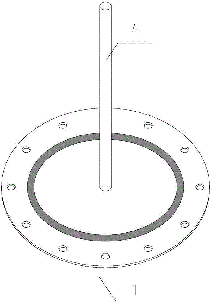
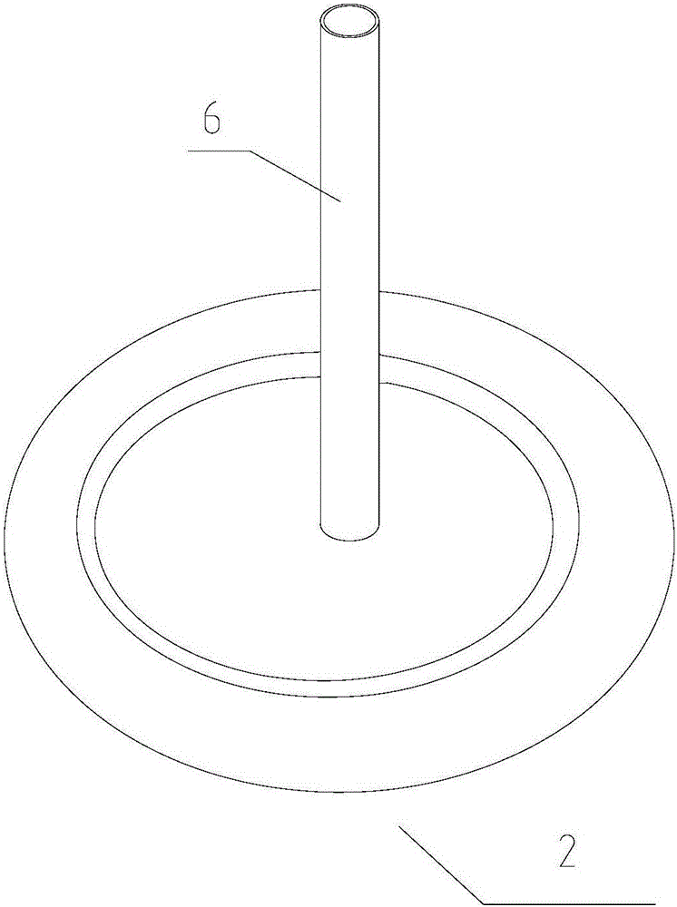
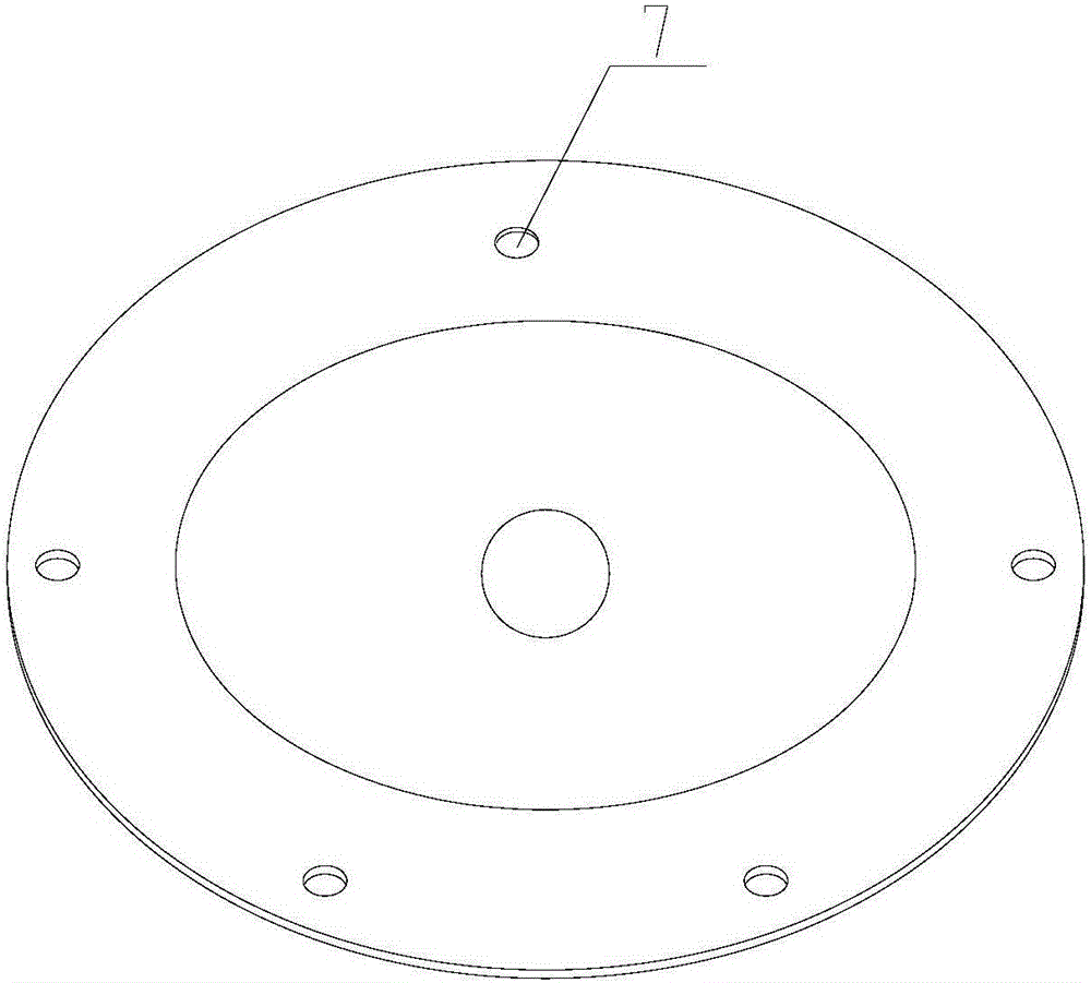
[0023] The new control cable pay-off frame is used to control e.g. Figure 4 The deployment of the cable coil 5 on the cable reel 3 is shown, including as figure 1 The shown fixed chassis 1 and the figure 2 Turntable 2 shown. The center of the fixed chassis 1 is welded with a drill rod 4 for nesting the cable reel 3 . The center of the rotary disk 2 is provided with a cylindrical hollow sleeve rod 6 for passing through the drill rod 4; the bottom of the rotary disk 2 is provided with a plurality of image 3 The rotating wheels 7 are shown, each of which is fixed by a screw.

[0024] Preferably, in this embodiment, the fixed chassis 1 is made of steel plate, and its diameter is 55-65 cm, which can bear enough weight to ensure that when the cable 5 is paid out, the entire pay-off rack device will not shake, dump. The height of the drill pipe 4 is 45-55 cm. Further, the diam...


PUM


Abstract

The invention discloses a new control cable pay-off frame, which is used to control the release of cable coils on a cable reel, and is characterized in that it includes a fixed chassis and a rotating disk sleeved on the fixed chassis; the central welding of the fixed chassis There is a drill rod used to put the cable reel; the center of the rotating disk is provided with a cylindrical hollow rod for passing through the drill rod; the bottom of the rotating disk is equipped with a plurality of Rotary wheels, each of which is fixed by a screw. The invention adopts a portable design, which is convenient for on-site use and portability; simple and convenient assembly, saving time; capable of laying out cables of different types; durable and convenient for maintenance.

Description

technical field [0001] The invention relates to the field of electric power, in particular to a novel control cable pay-off rack. Background technique [0002] Cables play a vital role in substations and each substation needs to use a lot of cables. Cable deployment is required in new substation infrastructure, substation expansion and technical overhaul projects. Casting a large number of cables is a complex and arduous work, and it is extremely difficult to complete only by manpower, so some devices are required to complete it. The cable distribution rack is one of the most commonly used devices in cable distribution. [0003] The cable release rack is the most common device in electric power, telecommunications and other construction projects. It plays an important role in projects that require cables to be released, such as new substation infrastructure and technical renovation and overhaul. The traditional cable pay-off rack is mainly composed of two triangular brack...

Claims


Application Information

Patent Timeline
Patent Type & Authority Applications(China)
IPC IPC(8): B65H49/30B65H75/22B65H75/18
CPCB65H49/30B65H75/18B65H75/22
Inventor 汪雷沈荣清袁则红宋根华宋毅徐照民张磊钱旭军张炳清付阳周宗学董国威赵俊邵涤球吴兴龙
Owner XUANCHENG POWER SUPPLY COMPANY OF STATE GRID ANHUI ELECTRIC POWER
Why Eureka
Try Eureka