Stress annealing method and device capable of accurately controlling annealing process parameters

An annealing process and stress annealing technology, applied in manufacturing tools, heat treatment process control, heat treatment equipment, etc., can solve the problem of difficulty in accurately controlling annealing process parameters such as stress and temperature, inability to accurately control the annealing state of materials, and difficulty in ensuring material performance consistency. and other problems, to achieve the effect of flexible and fast temperature control, small annealing cavity, and energy saving of temperature control.

Active Publication Date: 2016-06-22
ZHEJIANG NORMAL UNIVERSITY
View PDF5 Cites 9 Cited by
  • Summary
  • Abstract
  • Description
  • Claims
  • Application Information

AI Technical Summary

Problems solved by technology

[0003] The purpose of the present invention is to provide a stress annealing method and device, which aims to solve the factors such as the temperature gradient of the furnace and the thermal expansion and contraction of the material itself. It is difficult to accurately control the annealing process parameters such as stress and temperature, and the annealing state of the material cannot be accurately controlled. It is impossible to ensure that the entire plate of materials is annealed under the same conditions, and it is difficult to ensure the consistency of material properties

Method used


Image

  • Stress annealing method and device capable of accurately controlling annealing process parameters
  • Stress annealing method and device capable of accurately controlling annealing process parameters
  • Stress annealing method and device capable of accurately controlling annealing process parameters

Examples


Embodiment Construction

[0022] In order to make the object, technical solution and advantages of the present invention more clear, the present invention will be further described in detail below in conjunction with the examples. It should be understood that the specific embodiments described here are only used to explain the present invention, not to limit the present invention.

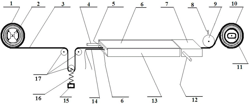
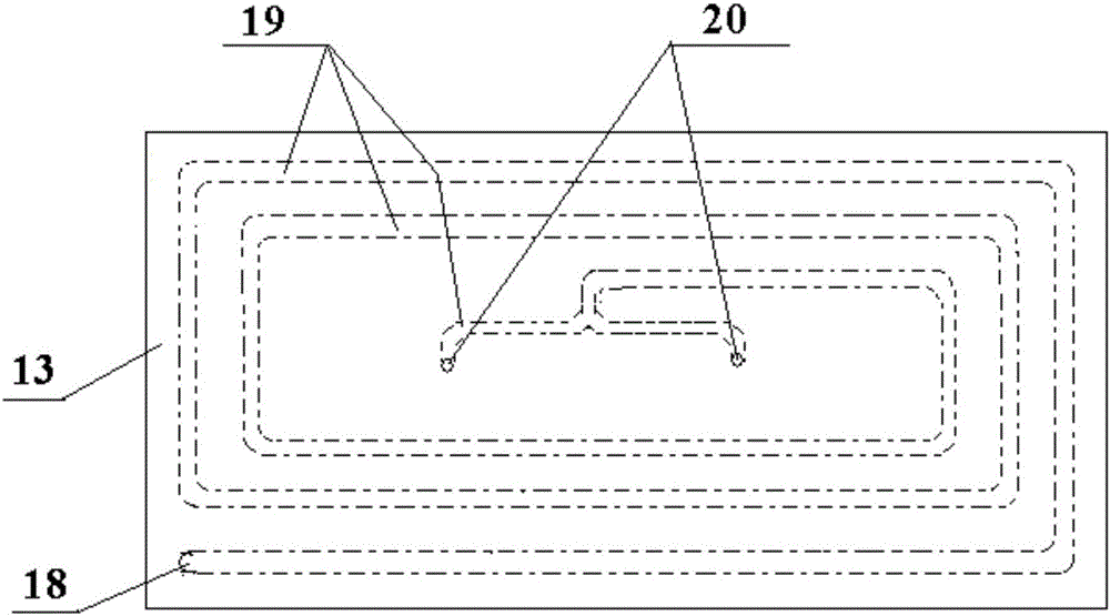
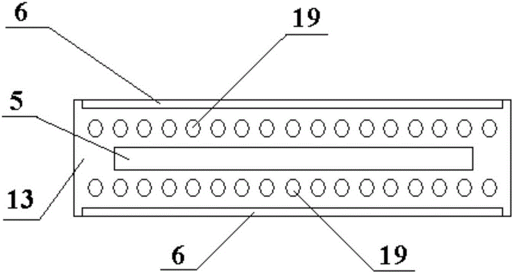
[0023] Attached below Figures 1 to 4 and specific embodiments to further describe the application principle of the present invention.

[0024] During the annealing process, the amorphous alloy material is automatically passed through the annealing chamber at a uniform speed, and the tensile stress, annealing temperature and transmission speed are automatically and precisely regulated online.

[0025] The present invention also takes following technical measures:

[0026] The annealing chamber is a channel-type annealing chamber 5, and the channel-type annealing chamber 5 is installed in the axial direction at the center ...


PUM


Abstract

The invention discloses a stress annealing method and device capable of accurately controlling annealing process parameters. During annealing, an amorphous alloy material is made to automatically pass through an annealing cavity at a constant speed, and the tensile stress, the annealing temperature and the conveying speed are automatically and accurately regulated and controlled online. The annealing cavity is small in size, stress control is flexible and accurate, temperature control is flexible, rapid and convenient, and the energy-saving advantage is achieved. In the prior art, a box type annealing cavity is adopted, the box type annealing cavity is large in size, an annealing position is away from a heat source, heat conductivity is poor, thick and large heat insulating walls are adopted by the cavity, and heat capacity is large, so that temperature control is slow and difficult, and energy consumption is large in the annealing process. The channel type annealing cavity is adopted, the cavity is small in size, the cavity walls are made of a high-heat-conductivity material, heat conduction is rapid, temperature control is flexible and rapid, and energy consumption is small. The dynamic annealing mode that an annealed material is conveyed to pass through the channel type annealing cavity at a constant speed is adopted, and compared with static annealing mode through box type annealing cavities commonly used at present, the advantages of accurate control over the annealing parameters and high uniformity of the batch material annealing effect are achieved.

Description

technical field [0001] The invention relates to the technical field of amorphous soft magnetic alloy materials, in particular to a stress annealing method and device capable of precisely controlling annealing process parameters. Background technique [0002] Amorphous soft magnetic alloy is the most important new magnetic material after ferrite and silicon steel sheet. The FeSiB amorphous alloy named "Metglas" was invented in 1982 and used as a transformer core. Compared with grain-oriented silicon steel sheets, the iron loss can be reduced by 1 / 3 to 1 / 5. In 1988, Yoshizawa et al. Nanocrystalline soft magnetic materials were prepared by annealing heat treatment of amorphous alloys, and the Fe 73.5 Cu 1 Nb 3 Si 13.5 B 9 "Finemet" alloy of typical composition. Finemet alloy has excellent comprehensive soft magnetic properties such as high magnetic permeability, low coercive force, high resistivity and low loss. Compared with traditional silicon steel materials, it has si...

Claims


Application Information

Patent Timeline
Patent Type & Authority Applications(China)
IPC IPC(8): C21D1/26C21D1/74C21D9/00C21D11/00
CPCC21D1/26C21D1/74C21D9/0062C21D11/00C21D11/005C21D2201/03
Inventor 方允樟叶慧群郑金菊吴锋民陈明肖飞孟繁雪
Owner ZHEJIANG NORMAL UNIVERSITY
Why Eureka
Try Eureka