Bridge thrusting slip device

A sliding device and jacking technology, which is applied in the direction of bridges, bridge construction, erection/assembly of bridges, etc., to achieve the effect of avoiding rapid changes in structural elevation, preventing void phenomenon, and good practicability

Inactive Publication Date: 2016-06-22
CHINA RAILWAY LIUYUAN GRP CO LTD +1
View PDF7 Cites 3 Cited by
  • Summary
  • Abstract
  • Description
  • Claims
  • Application Information

AI Technical Summary

Problems solved by technology

But currently on the market, there is no push sliding device that can meet the

Method used


Image

  • Bridge thrusting slip device
  • Bridge thrusting slip device
  • Bridge thrusting slip device

Examples


Example Embodiment

[0022] In order to make the technical features of the present invention easier to be understood clearly, the technical solutions of the present invention will be described in detail below with reference to the accompanying drawings and examples.
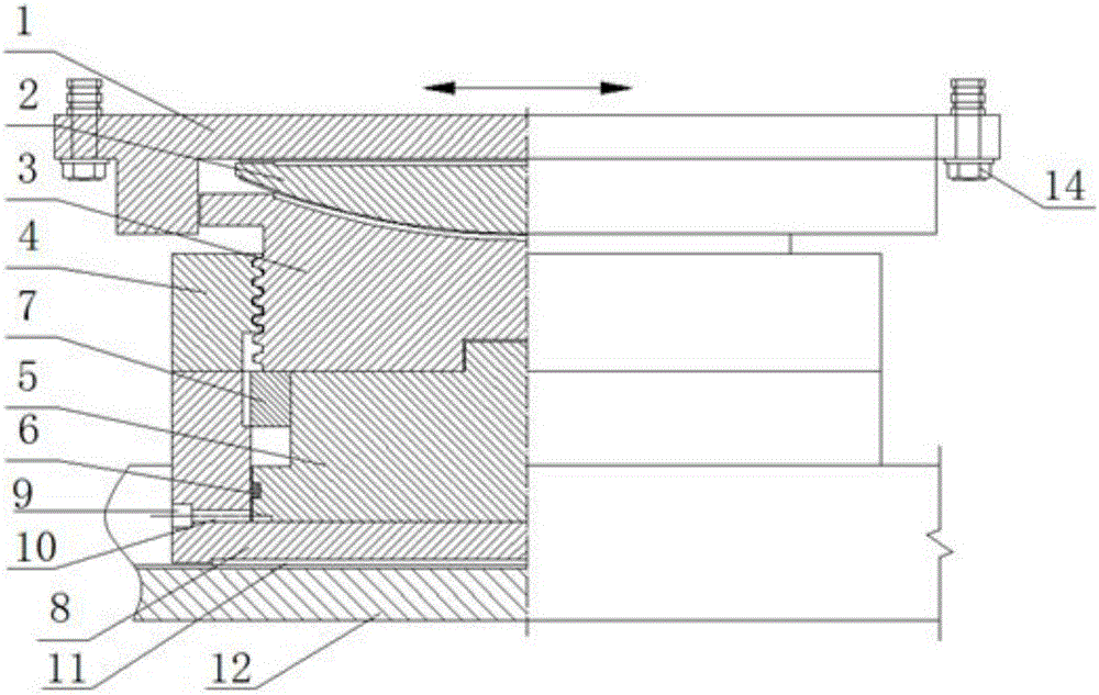
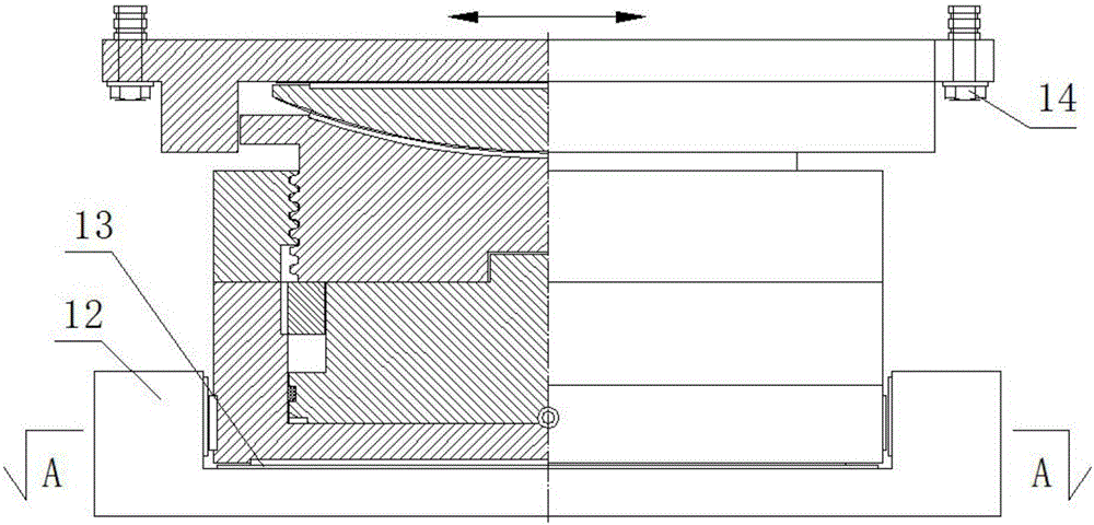
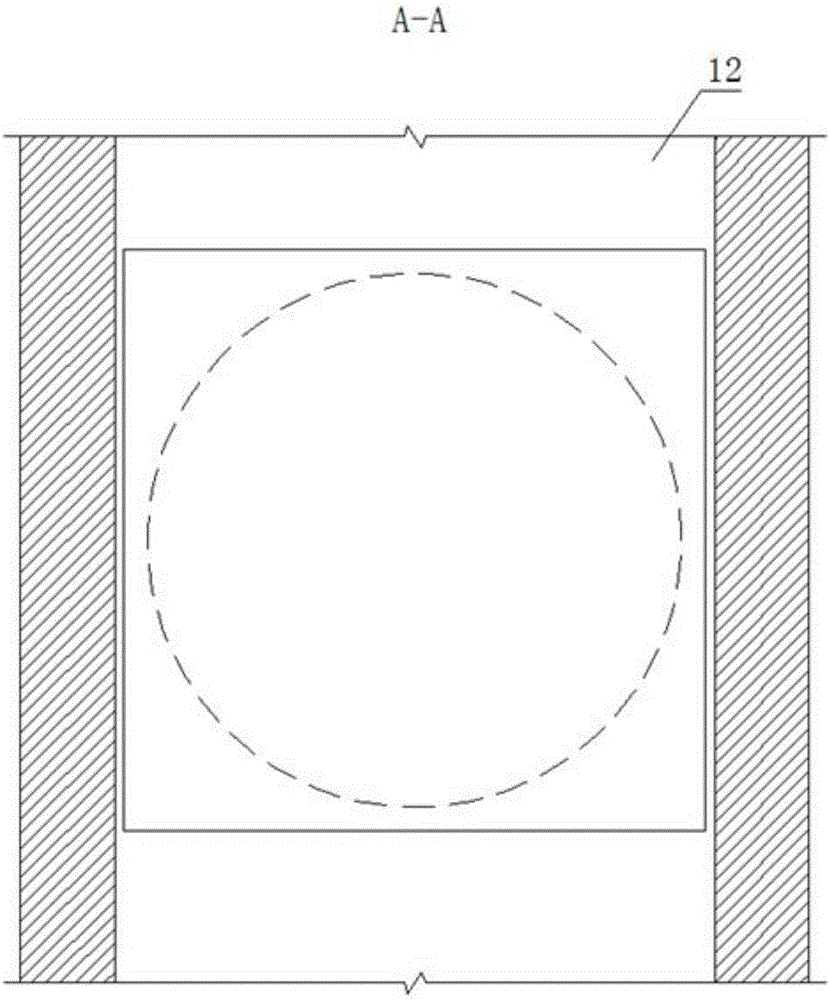
[0023] See figure 1 , figure 2 , image 3 , The bridge jacking slip device of the present invention includes an upper support plate 1 and a lower support plate 8, the upper support plate 1 and the lower support plate 8 are respectively provided with grooves; the groove of the upper support plate 1 A spherical crown lining plate 2 is installed inside, the upper plane of the spherical crown lining plate 2 is in contact with the bottom of the groove of the upper supporting plate 1, and the lower spherical surface of the spherical crown lining plate 2 is in radial direction with the stud 3. The end faces fit together, the stud 3 is threaded to the lock nut 4, the upper flange of the stud 3 is in contact with the side wall of the upper supp...


PUM


Abstract

The invention discloses a bridge pushing and sliding device, which comprises upper and lower support plates respectively provided with grooves, spherical crown liners installed in the grooves of the upper support plates, spherical crown liners The upper plane of the spherical crown liner is in contact with the bottom of the groove of the upper support plate, and the lower spherical surface of the spherical crown liner fits with the radial end surface of the stud. The stud is connected to the lock nut and its upper flange is in contact with the upper support plate. The side wall of the lower support plate is in contact with the side wall; the piston rod is installed in the groove of the lower support plate, the piston rod is provided with a sealing ring that forms a seal with the side wall of the lower support plate, and the side wall of the lower support plate is installed with a screw thread with the piston rod The connecting limit ring, the bottom of the lower support plate is provided with a hydraulic hole connected to the hydraulic system and communicated with the annular flow channel at the bottom of the piston rod, and the lower support plate is embedded in the slideway. Its advantages are: it can meet the two requirements of force measurement and height adjustment at the same time, and it can monitor the force situation of the vertical support points in real time, so as to grasp the dynamic changes of the vertical force of each support point of the bridge.

Description

technical field [0001] The invention belongs to the technical field of bridge pushing design and construction, and more specifically, the invention relates to a bridge pushing and sliding device used for bridge pushing and sliding operations. Background technique [0002] In the process of bridge pushing and sliding operations, ensuring the balance of the bridge structure and the uniform force of each supporting point is the key to successfully complete the pushing and sliding operations. [0003] In the process of bridge pushing and sliding, due to factors such as the elevation error generated in the construction of the slideway beams and the non-synchronous deflection deformation of multiple slideway beams, all the supporting points of the bridge will be affected by the pressure during the pushing and sliding process. The force is uneven, and even individual support points may be empty. All these factors will affect the stability of the bridge's push and slide, and increa...

Claims


Application Information

Patent Timeline
IPC IPC(8): E01D21/06
CPCE01D21/06
Inventor 鲁昭周津斌牛凤鸣李黎卢永涛刘向琼吴晓如苏杨代聚文王相贤王念才
Owner CHINA RAILWAY LIUYUAN GRP CO LTD
Why Eureka
Try Eureka