
Optical fiber vibration source recognition method, device, and system

An optical fiber and identification terminal technology, used in measuring devices, instruments, measuring ultrasonic/sonic/infrasonic waves, etc., can solve the problems of misidentification of vibration sources, multiple interference noises, etc., to avoid misidentification, effectively identify vibration sources, and improve reliability. sexual effect

Inactive Publication Date: 2016-06-22
惠州市明光实业有限公司
View PDF4 Cites 4 Cited by
  • Summary
  • Abstract
  • Description
  • Claims
  • Application Information

AI Technical Summary

Problems solved by technology

[0003] However, the environment where the optical fiber is located usually has a lot of interference noise, which leads to the non-stationary interference of the measured two-dimensional distribution parameters of time and space in the optical fiber signal, causing misidentification of the vibration source

Method used


Image

  • Optical fiber vibration source recognition method, device, and system
  • Optical fiber vibration source recognition method, device, and system
  • Optical fiber vibration source recognition method, device, and system

Examples


Embodiment Construction

[0027] In the following description, for the purpose of illustration rather than limitation, specific details such as a specific system structure, interface, technology, etc. are proposed for a thorough understanding of this application. However, it should be clear to those skilled in the art that this application can also be implemented in other embodiments without these specific details. In other cases, detailed descriptions of well-known devices, circuits, and methods are omitted to avoid unnecessary details from obstructing the description of this application.

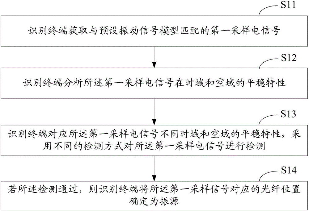
[0028] See figure 1 , A flowchart of an embodiment of the method for identifying optical fiber vibration sources according to the present invention, the method includes:

[0029] S11: The identification terminal obtains the first sampled electrical signal matching the preset vibration signal model.

[0030] Wherein, the first sampled electrical signal is obtained by converting the first sampled optical signal, and the fi...


PUM


Abstract

The invention discloses an optical fiber vibration source recognition method, device and system. The method includes the steps of: obtaining a first sampling electric signal matching a preset vibration signal model by a recognition terminal, wherein the first sampling electric signal is acquired by converting a first sampling optical signal, and the first sampling optical signal is obtained by sampling an optical signal reflected by an optical fiber; analyzing the stability characteristics of the first sampling electric signal in the time domain and the space domain; employing different detection modes to detect the first sampling electric signal based on the different stability characteristics of the first sampling electric signal in the time domain and the space domain; and if the detection passes, determining an optical fiber position corresponding to the first sampling electric signal as a vibration source. Through the above mode, effective vibration source recognition is realized aiming at different environments, and the false recognition of the vibration source is avoided.

Description

Technical field [0001] The present invention relates to the field of optical fiber communication, in particular to an optical fiber vibration source identification method, device and system. Background technique [0002] With the development of optical fiber processing technology, optical fibers can be used to detect surrounding environmental conditions, such as whether an object passes by, and what the object is. When the detection fiber is affected by external interference and vibrates, part of the characteristics of the transmitted light in the fiber will change. The identification terminal collects the signal, analyzes the characteristics of the collected signal to determine the change in its optical characteristics, and then detects the location of the vibration source , And then can realize the monitoring of the environment. [0003] However, the environment in which the optical fiber is located usually has a lot of interference noise, which leads to non-stationary interfere...

Claims


Application Information

Patent Timeline
IPC IPC(8): G01H9/00
CPCG01H9/004
Inventor 赵银凤刘博宇魏照聂鑫刘本刚李建彬
Owner 惠州市明光实业有限公司
Features
  • Generate Ideas
  • Intellectual Property
  • Life Sciences
  • Materials
  • Tech Scout
  • Unparalleled Data Quality
  • Higher Quality Content
  • 60% Fewer Hallucinations
Learn More