An automatic centering system for wind power speed increaser test test

A technology of automatic alignment and test testing, applied in the direction of machine gear/transmission mechanism testing, etc., can solve the problems of long time, low production efficiency, affecting the development and growth of wind power speed-increasing machines

Active Publication Date: 2018-05-18
沈阳恒久安泰智能制造与机器人系统技术有限公司
View PDF6 Cites 0 Cited by
  • Summary
  • Abstract
  • Description
  • Claims
  • Application Information

AI Technical Summary

Problems solved by technology

The first is the fixed type. The speed increaser and the motor are respectively fixed on the foundation, and the low-speed end of the accompanying test speed increaser is aligned with the tested speed increaser by manually adding gaskets and screwing the lateral screws. The alignment method of the electric (generator) engine and the accompanying (tested) speed increaser is the same as that of the low-speed end of the two speed increasers. This connection method takes a long time and the production efficiency is low.
[0004] The second way is the mobile type. The motor, generator, accompanying test speed increaser, and test speed increaser are respectively installed on their respective mobile platforms. Each mobile platform has degrees of freedom in the axial, radial and vertical directions. , the three-dimensional movement adopts a servo mechanism. The servo mechanism mainly includes a guide rail, a slider, a screw, and a servo motor. Although this structure can meet the requirements for quick adjustment and alignment, this solution is due to the point contact or line contact of the guide rail (the guide rail The rolling body of the slider is spherical or cylindrical), and the rigidity is very poor, which causes abnormal vibration during the loading test. This problem is a common problem in the industry, and there is no solution
[0005] The abnormal vibration problem caused by the low efficiency or poor rigidity of the wind power speed up test system has affected the development of the wind power speed up industry
In view of this situation, it is imminent to design a test centering system for wind power speed increaser, which can not only meet the problem of rapid adjustment, but also solve the problem of abnormal vibration during loading test due to poor rigidity

Method used


Image

  • An automatic centering system for wind power speed increaser test test
  • An automatic centering system for wind power speed increaser test test
  • An automatic centering system for wind power speed increaser test test

Examples


Embodiment Construction

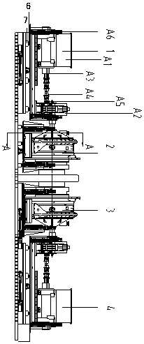
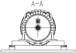
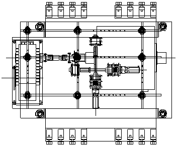
[0031] Such as Figure 1-9 As shown, this specific embodiment adopts the following technical solutions: it comprises 4 modules, respectively A module 1, B module 2, C module 3 and D module 4, A module 1, B module 2, C module 3 and D module 4 connected sequentially, the A module 1 includes the motor A1, the process gearbox A2, the torque sensor A3, the universal coupling A4 and the connecting flange A5, the torque sensor A3 is installed on the motor A1, and the front end of the torque sensor A3 is connected to the One end of the universal coupling A4 is connected, and the other end of the universal coupling A4 is connected with the connecting flange A5, and the connecting flange A5 is set on the process gearbox A2, and the relative position of the motor A1 and the torque sensor A3 is adjusted The alignment process remains the same.

[0032] As preferably, the A module 1 also includes four vertical servo structures A6 and radial adjustment bases A7, one end of the motor A1 and ...


PUM


Abstract

The invention discloses an automatic centering system for testing a speed-up gearbox for wind power generation, and relates to the technical field of accurate centering, mounting and debugging of heavy machinery with weight of tens of tons to hundreds of tons. An A module, a B module, a C module and a D module are successively connected. The A module comprises a motor, a process gearbox, a torque sensor, a unidirectional coupling and a connecting flange. The torque sensor is mounted on the motor. The front end of the torque sensor is connected with one end of the unidirectional coupling. The other end of the unidirectional coupling is connected with the connecting flange. Furthermore the connecting flange is arranged on the process gearbox. Relative positions between the motor and the torque sensor are kept unchanged in the adjusting centering process. A test platform satisfies a requirement of performing loading test on various different types of speed-up gearboxes. The assembled speed-up gearbox can be directly placed on the platform for realizing accurate connection adjustment. The automatic centering system settles a problem of vibration interference in speed-up gearbox loading test in common quick adjustment application cases. An operator utilizes a remote control handle for driving a servo mechanism to act. High portability and quick adjustment are realized.

Description

technical field [0001] The invention relates to an automatic centering system for test and test of a wind power speed increaser, which relates to the technical field of precise centering, installation and debugging of heavy machinery weighing tens to hundreds of tons. Background technique [0002] The centering system of the speed increaser loading test bench is generally interconnected (back-to-back) by the low-speed (input) end of the accompanying test speed increaser and the tested speed increaser through a (drum-shaped gear, etc.) The high-speed (output) end of the machine is connected to the motor (via a coupling, torque sensor, etc.). [0003] At present, there are generally two ways to adjust the centering of the loading test bench of the speed increaser at home and abroad. The first is the fixed type. The speed increaser and the motor are respectively fixed on the foundation, and the low-speed end of the accompanying test speed increaser is aligned with the tested s...

Claims


Application Information

Patent Timeline
IPC IPC(8): G01M13/02
CPCG01M13/02
Inventor 吴佳梁苏健孙长青
Owner 沈阳恒久安泰智能制造与机器人系统技术有限公司
Why Eureka
Try Eureka