Method and device for jointly calibrating parameters of visible light camera and infrared camera

An infrared camera and joint calibration technology, which is applied in image data processing, instruments, calculations, etc., can solve the problems of increasing manpower and material costs for obtaining camera parameters, and achieve the effect of reducing calibration costs and improving efficiency

Active Publication Date: 2016-06-22
CHINA FORESTRY STAR BEIJING TECH INFORMATION CO LTD
View PDF4 Cites 34 Cited by
  • Summary
  • Abstract
  • Description
  • Claims
  • Application Information

AI Technical Summary

Problems solved by technology

[0004] However, in order to obtain camera parameters, a calibration board needs to be specially designed and produced, which will increase the manpower and material costs of obtaining camera parameters

Method used


Image

  • Method and device for jointly calibrating parameters of visible light camera and infrared camera
  • Method and device for jointly calibrating parameters of visible light camera and infrared camera
  • Method and device for jointly calibrating parameters of visible light camera and infrared camera

Examples


Embodiment 1

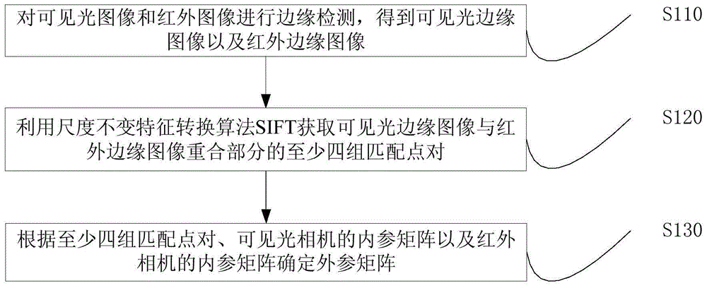
[0022] figure 1 It is a flow chart of a joint calibration method for parameters of a visible light camera and an infrared camera provided by Embodiment 1 of the present invention. This embodiment is applicable to the case of calibrating the parameters of a visible light camera and an infrared camera. Capability of the terminal to execute, such as a personal computer (PersonalComputer, PC), notebook computer, tablet computer, etc., the method specifically includes the following steps:

[0023] S110. Perform edge detection on the visible light image and the infrared image to obtain a visible light edge image and an infrared edge image.

[0024] When performing edge detection on visible light images, edge detection based on search or edge detection based on zero crossing can be used. The search-based edge detection method detects the boundary by finding the maximum and minimum values ​​in the first derivative of the image, usually locating the boundary in the direction of the la...

Embodiment 2

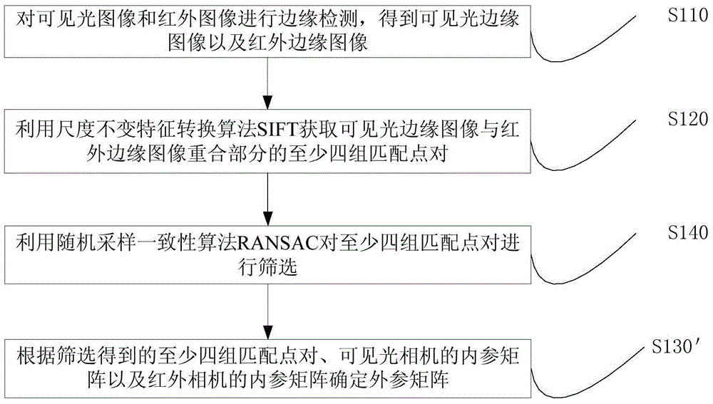
[0054] figure 2 It is a flow chart of a method for joint calibration of parameters of a visible light camera and an infrared camera provided in Embodiment 2 of the present invention. Preferably, at S120, use the scale-invariant feature transformation algorithm SIFT to obtain at least the overlapping portion of the visible light edge image and the infrared edge image After four sets of matching point pairs, also include:

[0055] S140. Use the random sampling consensus algorithm RANSAC to screen at least four sets of matching point pairs.

[0056] The Random Sampling Consensus (RANdomSAmpleConsensus, RANSAC) algorithm achieves the goal by repeatedly selecting a set of random subsets in the data. The selected subsets are assumed to be interior points and verified by the following method:

[0057] S1. Construct a prediction model, and the prediction model is adapted to a hypothetical interior point. The prediction model can be generated according to at least four sets of matc...

Embodiment 3

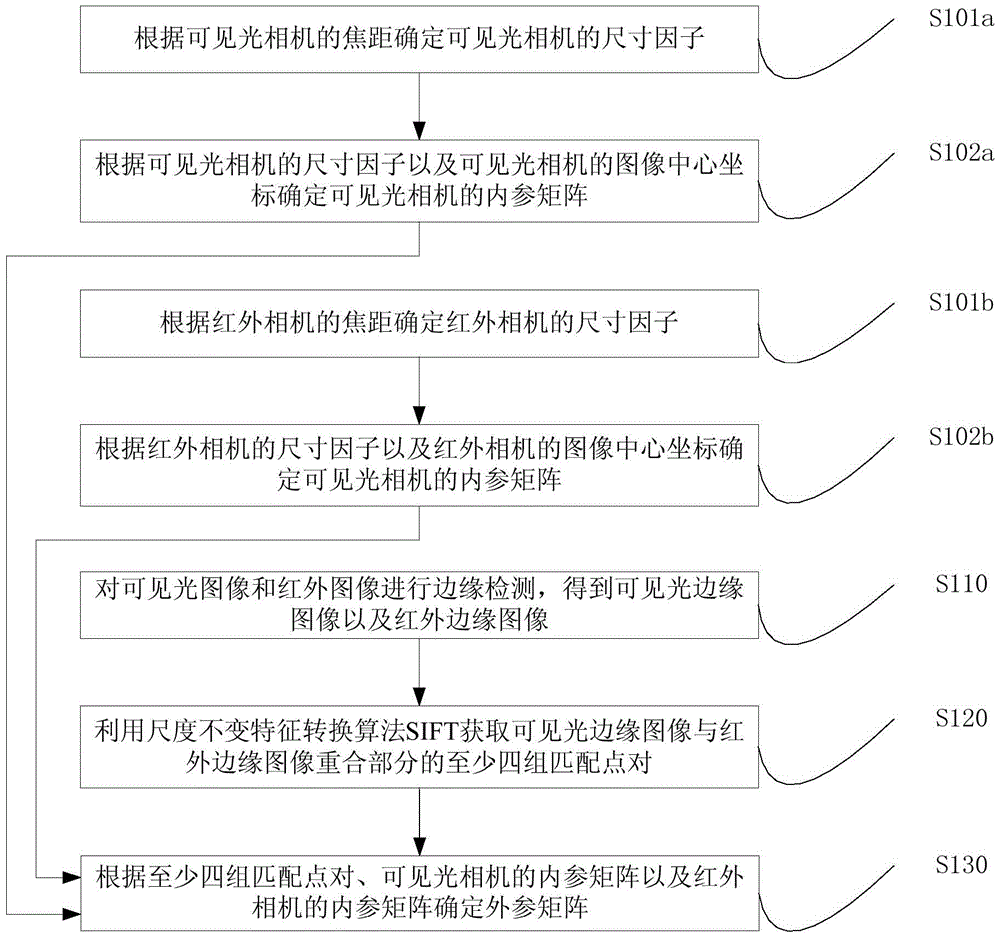
[0067] image 3 It is a flowchart of a joint calibration method for parameters of a visible light camera and an infrared camera provided in Embodiment 3 of the present invention. Optionally, at S130, according to the at least four sets of matching point pairs, the internal reference matrix of the visible light camera, and the Before the internal reference matrix of the infrared camera determines the external reference matrix, the method also includes:

[0068] S101a. Determine the size factor of the visible light camera according to the focal length of the visible light camera.

[0069] The size factors for visible light cameras include the u-axis size factor c x2 and v-axis size factor c y2 . u-axis size factor c x2 is the u-axis focal length f cx2 Divide by the v-axis focal length f cy2 . v-axis size factor c y2 is the v-axis focal length f cy2 divided by the u-axis focal length f cx2 .

[0070] S102a. Determine an internal reference matrix of the visible light ca...


PUM


Abstract

The invention discloses a method and device for jointly calibrating the parameters of a visible light camera and an infrared camera. The method comprises steps of: detecting the edges of a visible light image and an infrared image to obtain a visible light edge image and an infrared edge image; acquiring at least four groups of matched point pairs of the visible light edge image and the infrared edge image by using a scale invariant feature transform (SIFT) algorithm; and determining an extrinsic parameter matrix according to the at least four groups of matched point pairs, the intrinsic parameter matrix of the visible light camera, and the intrinsic parameter matrix of the infrared camera. The method and the device may acquire the matched point pairs in the visible light edge image and the infrared edge image without a calibration board and determine the extrinsic parameter matrix without the calibration board so as to reduce the calibration cost of camera parameters. Further, when a focal length of the camera is changed, the extrinsic parameter matrix can be determined without camera position adjustment so that parameter calibration efficiency is increased.

Description

technical field [0001] Embodiments of the present invention relate to a camera parameter calibration technology, in particular to a method and device for joint calibration of parameters of a visible light camera and an infrared camera. Background technique [0002] In applications such as multispectral photogrammetry, remote sensing, and target monitoring, since visible light cameras can obtain rich texture information, and infrared thermal imaging cameras can obtain temperature information, the joint measurement of visible light cameras and infrared cameras has been widely used. [0003] In the prior art, a planar calibration board with a heating device is firstly designed and manufactured, then the corresponding information of visible light images and infrared images is collected through the calibration board, and finally the camera parameters are obtained by traditional calibration methods. [0004] However, in order to obtain the camera parameters, a calibration board ne...

Claims


Application Information

Patent Timeline
Patent Type & Authority Applications(China)
IPC IPC(8): G06T7/00
CPCG06T2207/10036G06T2207/10048
Inventor 李波汪洋耿莹蔡宇黄艳金
Owner CHINA FORESTRY STAR BEIJING TECH INFORMATION CO LTD
Why Eureka
Try Eureka