Flow battery system structure

A liquid flow battery and system structure technology, applied in the direction of regenerative fuel cells, etc., can solve the problems of high equipment cost, large power consumption, and affecting battery performance, so as to improve operating efficiency, restore performance, and avoid power loss and interruption The effect of system operation

Active Publication Date: 2016-06-22
DALIAN RONGKE POWER
View PDF5 Cites 6 Cited by
  • Summary
  • Abstract
  • Description
  • Claims
  • Application Information

AI Technical Summary

Problems solved by technology

Due to the permeability of the hydrogen ion exchange membrane, the vanadium ions of the positive and negative electrodes continuously migrate with the water molecules and are accompanied by side reactions. After the all-vanadium redox flow battery system undergoes long-term charge and discharge cycles, a large amount of V5+ ions are left on the positive electrode. The V5+ ions will combine with the surrounding sulfate radicals to form some kind of precipitation, causing the discharge capacity of the flow battery to drop below 70% of the initial capacity, seriously affecting the performance of the battery
The way to solve this technical problem in the prior art is generally to equip the flow battery system with high-power electrolysis equipment to remove sediment regularly, which leads to high equipment cost, large power consumption, and large material and manpower consumption.

Method used


Image

  • Flow battery system structure
  • Flow battery system structure
  • Flow battery system structure

Examples


Embodiment Construction

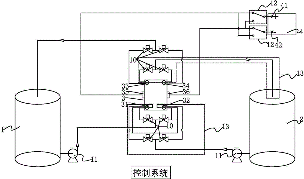
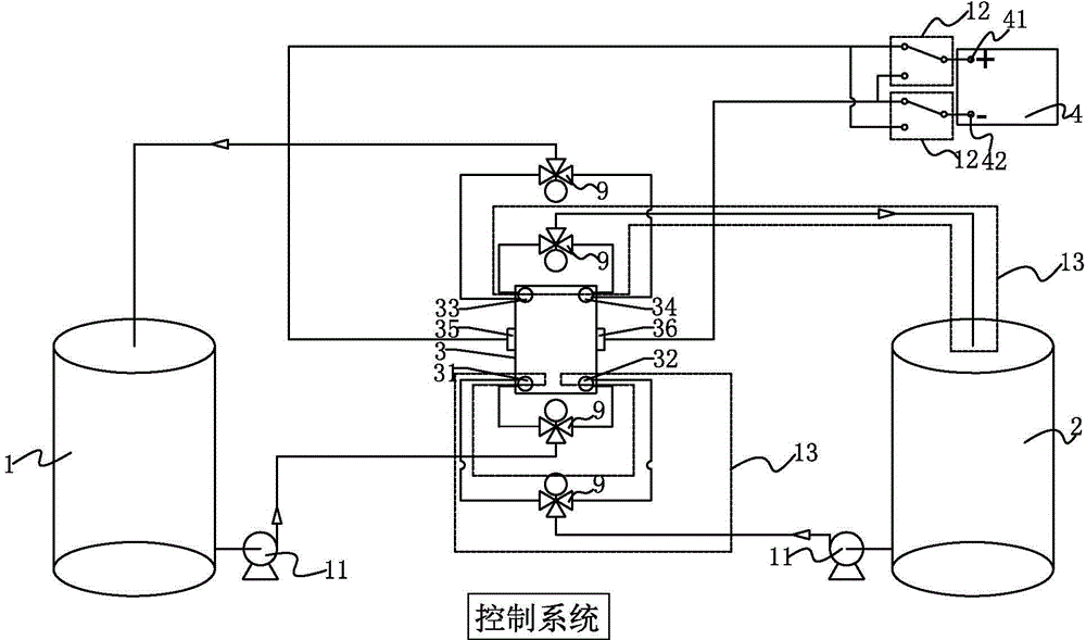
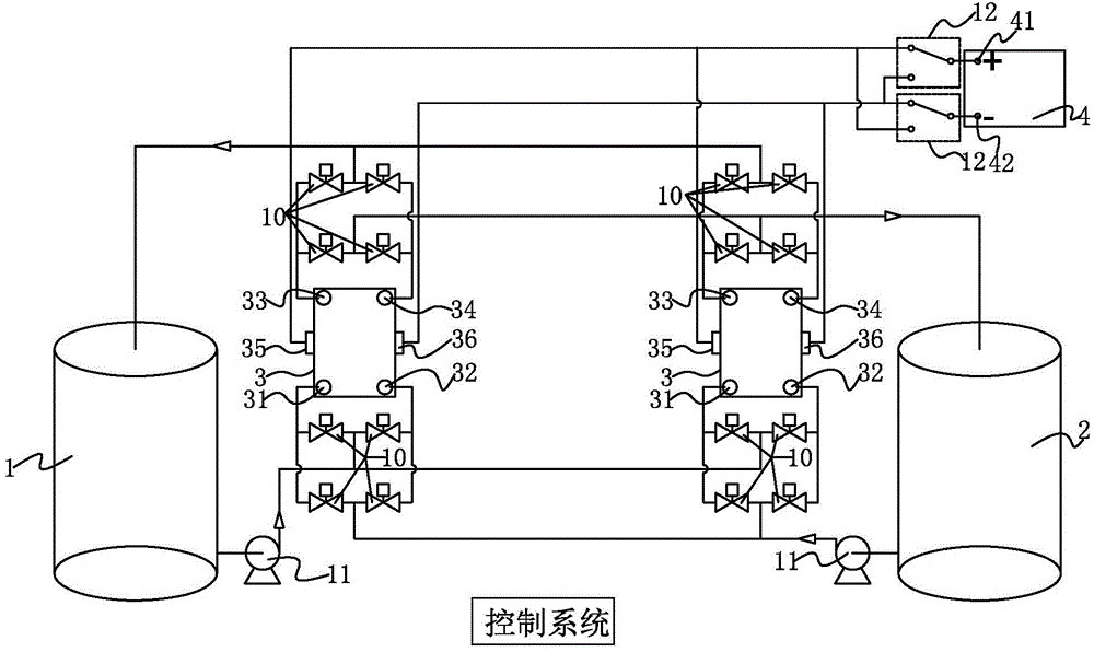
[0034] Such as figure 1 and figure 2The shown structure of a liquid flow battery system includes: at least one electric stack 3, a positive electrode electrolyte storage tank 1, a negative electrode electrolyte storage tank 2, and equipment 4 for power supply and / or electricity use; the electric stack 3 has The first electrical input and output end 35, the second electrical input and output end 36, the first electrolyte inlet 31, the second electrolyte inlet 32, the first electrolyte outlet 33 and the second electrolyte outlet 34; the positive electrode electrolyte storage Both the tank 1 and the negative electrode electrolyte storage tank 2 are connected to the first electrolyte inlet 31 and the second electrolyte inlet 32 ​​of the stack 3; the first electrolyte outlet 33 and the second electrolyte outlet 33 of the stack 3 The outlets 34 are all connected to the positive electrode electrolyte storage tank 1 and the negative electrode electrolyte storage tank 2; the device 4...


PUM


Abstract

The invention discloses a flow battery system structure. The flow battery system structure comprises at least one pile, a positive electrolyte storage tank, a negative electrolyte storage tank and a power supply and/or power utilization device, wherein the stack is provided with a first electric input/output end, a second electric input/output end, a first electrolyte inlet, a second electrolyte inlet, a first electrolyte outlet and a second electrolyte outlet, the positive electrolyte storage tank and the negative electrolyte storage tank are both connected with the first electrolyte inlet and the second electrolyte inlet of the stack, the first electrolyte outlet and the second electrolyte outlet are both connected with the positive electrolyte storage tank and the negative electrolyte storage tank, the device is provided with a positive wiring end and a negative wiring end, and the first electric input/output end and the second electric input/output of the stack both can be connected with the positive wiring end or the negative wiring end. By the flow battery system structure, the performance of an on-line battery restoring system is achieved.

Description

technical field [0001] The invention relates to the field of liquid flow batteries, in particular to a structure of a liquid flow battery system. Background technique [0002] With the increasing shortage of fossil energy and the increasingly serious problem of environmental pollution, human beings gradually pin their hopes for future energy on the development and utilization of renewable clean energy such as wind energy and solar energy. Instability and discontinuity, therefore, it is necessary to collect the low-quality current generated by these energy sources for smooth, stable and controllable output in order to meet the needs of user terminals and realize the real application of renewable energy. [0003] Flow battery is an emerging secondary energy storage battery. Unlike other ordinary batteries that store active materials inside the battery, it stores the electrolyte in a storage tank outside the stack, which is realized through a fluid pump and a fluid delivery pip...

Claims


Application Information

Patent Timeline
Patent Type & Authority Applications(China)
IPC IPC(8): H01M8/18
CPCY02E60/50
Inventor 邹毅张华民孙旻张涛马相坤孙振涛
Owner DALIAN RONGKE POWER
Why Eureka
Try Eureka