
Separation-connection locking apparatus for transmission shaft of drawer holder base of universal circuit breaker

A locking device and transmission shaft technology, applied in switchgear, pull-out switch cabinet, electrical components, etc., can solve the problem of damage to the crank handle or the transmission shaft or the locking device, the collision between the transmission shaft and the locking device, and affecting the transmission accuracy of the components and other problems, to achieve the effect of simple structure, stable transmission and simplified connection structure

Active Publication Date: 2016-06-22
乐清市振弘开关有限公司
View PDF6 Cites 9 Cited by
  • Summary
  • Abstract
  • Description
  • Claims
  • Application Information

AI Technical Summary

Problems solved by technology

[0003] With the above mechanism, because the locking mechanism will instantly lock the transmission shaft at three positions, workers usually use a lot of force when operating the crank handle, and at this time if the circuit breaker is just in the "connected" position and "disconnected" position And near any position in the "test" position, if the worker still operates vigorously, it will cause a strong collision between the transmission shaft and the locking device. If this method is often used, it will affect the accuracy of the transmission of each component. Will cause damage to the crank or drive shaft or locking mechanism

Method used


Image

  • Separation-connection locking apparatus for transmission shaft of drawer holder base of universal circuit breaker
  • Separation-connection locking apparatus for transmission shaft of drawer holder base of universal circuit breaker
  • Separation-connection locking apparatus for transmission shaft of drawer holder base of universal circuit breaker

Examples


Embodiment Construction

[0030] Below in conjunction with specific embodiment and accompanying drawing, the present invention will be further described:

[0031] The present invention will now be further described in conjunction with the accompanying drawings, which are simplified schematic diagrams only to schematically illustrate the basic structure of the present invention, so they only show the configurations related to the present invention.

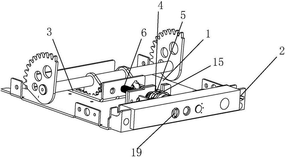
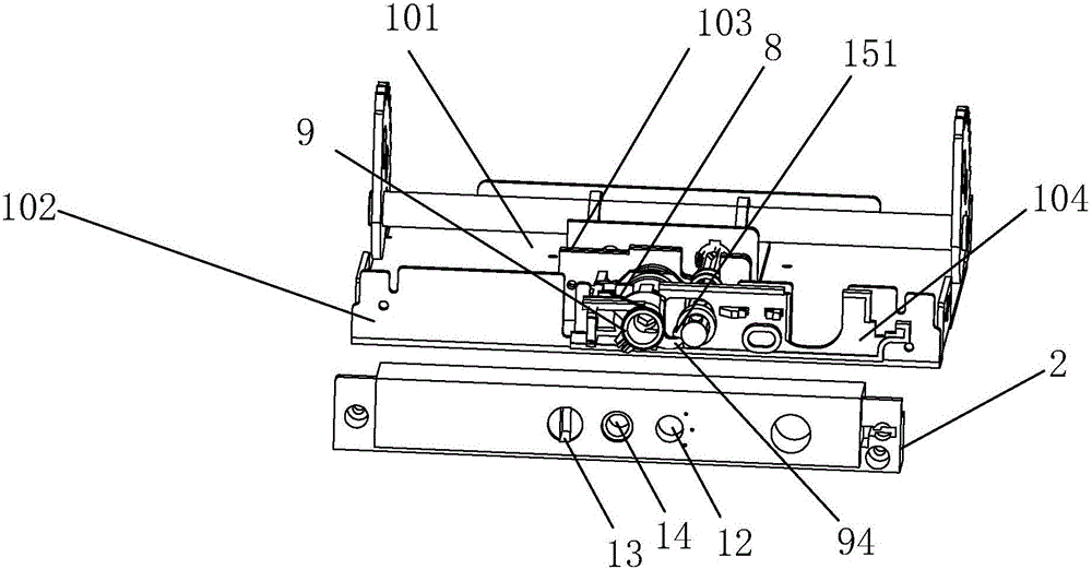
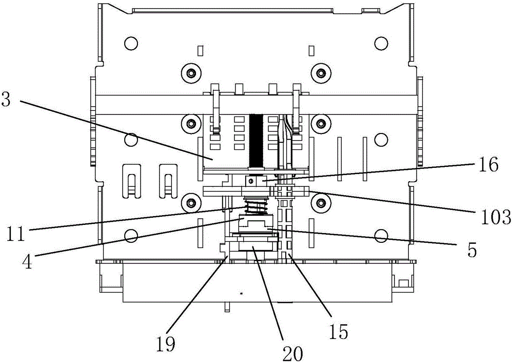
[0032] Such as Figure 1-5As shown, the present invention is a clutch locking device for the rotating shaft of the drawer seat base of a universal circuit breaker, which includes a drawer seat 1, a surface frame 2, a carriage 3, a clutch buckle I4, a clutch buckle II5, a transmission shaft I6, a transmission shaft II7, Propelling device, torsion spring 8, limiter 9, spring I10, spring II11 and rocking handle (not shown in the rocking handle figure).

[0033] The drawer base 1 includes a bottom plate 101 , a panel 102 , a positioning portion 103 and a clamp...


PUM


Abstract

The invention discloses a separation-connection locking apparatus for a transmission shaft of a drawer holder base of a universal circuit breaker. The separation-connection locking apparatus comprises a transmission shaft I, a transmission shaft II, a separation-connection buckle I, a separation-connection buckle II, a pushing apparatus, a limiting part, an energy storage part and a reset apparatus, wherein the transmission shaft is used for driving a dragging plate to slide; the transmission shaft II is rotationally connected with the drawer holder; the separation-connection buckle I is in transmission connection with the transmission shaft I; the separation-connection buckle II is connected with the transmission shaft II and is driven by the transmission shaft II to rotate; the pushing apparatus is used for pushing the separation-connection buckle I or the separation-connection buckle II to move to enable the separation-connection buckle I and the separation-connection buckle II to be clamped so as to form transmission connection; the limiting part is used for locking the pushing apparatus under the action of the energy storage part to enable the clamping state of the separation-connection buckle I and the separation-connection buckle II to be stable; a rotation shaft is provided with a convex part I; when the circuit breaker body is in an operating position, the limiting part is pushed to remove the locking state of the pushing apparatus; and the reset apparatus enables the separation-connection buckle I and the separation-connection buckle II to be separated when the locking state of the pushing apparatus is removed. The separation-connection locking apparatus has the beneficial effects that the collisions of parts in the draw holder can be reduced, the service life can be prolonged and the precision can be improved.

Description

technical field [0001] The invention relates to a clutch locking device for a drive shaft in a base of a drawer seat of a universal circuit breaker. Background technique [0002] Drawer type circuit breakers or frame type circuit breakers or universal circuit breakers are widely used in power distribution appliances. The circuit breaker body of this type of circuit breaker is usually installed in the drawer seat. The transmission shaft, the carriage mounted on the drawer seat linearly and slidably to drive the movement of the circuit breaker body, the rotating shaft pivotally mounted on the drawer seat, are used for when the circuit breaker body is in the "connected" position, "disconnected" position and "test" When in any position of the position, the locking mechanism that locks the transmission shaft so that the transmission shaft cannot rotate, the unlocking mechanism that is used to release the locked state of the locking mechanism, and the rocker that is connected with...

Claims


Application Information

Patent Timeline
Patent Type & Authority Applications(China)
IPC IPC(8): H02B11/133
CPCH02B11/133Y02E60/16
Inventor 章顺勤
Owner 乐清市振弘开关有限公司
Features
  • Generate Ideas
  • Intellectual Property
  • Life Sciences
  • Materials
  • Tech Scout
  • Unparalleled Data Quality
  • Higher Quality Content
  • 60% Fewer Hallucinations
Learn More