Spectrum sharing method and communication site
A communication site and spectrum sharing technology, applied in wireless communication, electrical components, network planning, etc., can solve the problems of reducing spectrum utilization, violating the configurable wireless system to improve spectrum utilization, system configuration failure, etc., to reduce signaling Interaction overhead and processing delay, avoid network coexistence problems, and improve the effect of spectrum utilization
- Summary
- Abstract
- Description
- Claims
- Application Information
AI Technical Summary
Problems solved by technology
Method used
Image
Examples
no. 1 example
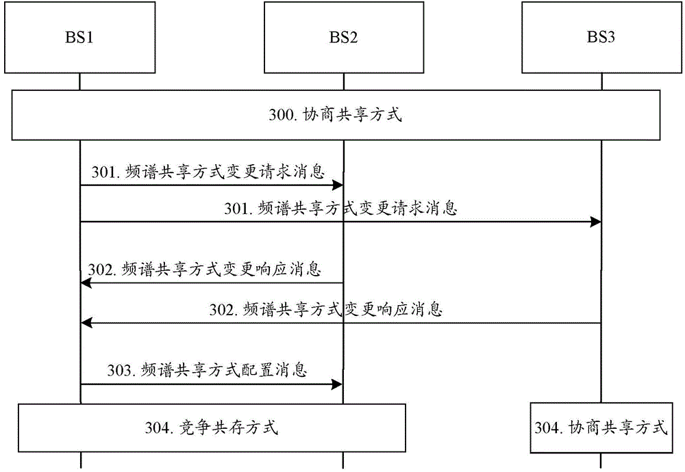
[0124] In the first embodiment, it is assumed that the communication site is base station 1 (BS1), and the relevant communication sites include BS2 and BS3; in this embodiment, it is assumed that BS1, BS2, and BS3 initially occupy the free spectrum f1 in time division through negotiation and sharing, and BS1 initiates spectrum sharing Mode Change Request. The specific process is as image 3 shown, including:
[0125] Step 300: BS1, BS2, and BS3 initially operate in a negotiation and sharing mode.
[0126] Specifically, BS1, BS2, and BS3 determine through negotiation that the time domain occupancy of frequency spectrum f1 in a unit time is as follows: Figure 4 as shown, Figure 4 It is a schematic diagram of the resource configuration before the change of the spectrum sharing method in the first embodiment of the present invention, which is repeated in the next time unit Figure 4 The time domain allocation shown. Wherein, the time domain resources indicated by the shaded...
no. 2 example
[0141] In the second embodiment, in this embodiment, it is assumed that BS1, BS2, BS3, and BS4 initially time-divisionally occupy the free spectrum f1 through negotiation and sharing, and BS1 initiates a spectrum sharing mode change request. The specific process is as Figure 6 shown, including:
[0142] Step 600: BS1, BS2, BS3, and BS4 initially operate in a negotiation and sharing mode.
[0143] Specifically, BS1, BS2, BS3, and BS4 determine through negotiation that the time domain occupancy of frequency spectrum f1 in a unit time is as follows Figure 7 as shown, Figure 7 It is a schematic diagram of the resource configuration before the change of the spectrum sharing method in the second embodiment of the present invention, which is repeated in the next time unit Figure 7 The time domain allocation shown. Wherein, the time-domain resources represented by the shaded part are the time-domain resources allocated to the corresponding BS, and in this time-domain resource ...
no. 5 example
[0186] In the fifth embodiment, it is assumed that:
[0187] The BS2 response message includes: BS2's device identifier 003, negative acknowledgment Nack;
[0188] The response message of BS3 includes: the device identifier of BS3 003, and the negative acknowledgment Nack.
[0189] That is to say, in the fifth embodiment, both BS2 and BS3 do not agree to switch to the competitive sharing mode.
[0190] Step 1003: After receiving the spectrum sharing mode change response message from BS2 and BS3, BS1 determines not to change the spectrum sharing mode, and still shares spectrum f1 with BS2 and BS3 through negotiation. ; and send spectrum sharing mode configuration messages to BS2 and BS3 respectively, to indicate that the spectrum sharing mode remains unchanged.
[0191] Step 1004: BS1, BS2, and BS3 still work in the negotiated sharing mode.
[0192] It should be noted that in this embodiment, neither BS2 nor BS3 accepts the spectrum sharing mode change request of BS1, theref...
PUM
 Abstract
Description
Claims
Application Information
 - R&D
- Intellectual Property
- Life Sciences
- Materials
- Tech Scout
- Unparalleled Data Quality
- Higher Quality Content
- 60% Fewer Hallucinations
Browse by: Latest US Patents, China's latest patents, Technical Efficacy Thesaurus, Application Domain, Technology Topic, Popular Technical Reports.
© 2025 PatSnap. All rights reserved.Legal|Privacy policy|Modern Slavery Act Transparency Statement|Sitemap|About US| Contact US: help@patsnap.com


