A spectrum sharing method and communication site

A spectrum sharing, communication site technology, applied in wireless communication, electrical components, network planning, etc., can solve the problems of reducing spectrum utilization, violating configurable wireless system to improve spectrum utilization, system configuration failure, etc., to reduce signaling Interaction overhead and processing delay, avoid network coexistence problems, and improve the effect of spectrum utilization

Active Publication Date: 2020-12-15
ZTE CORP
View PDF5 Cites 0 Cited by
  • Summary
  • Abstract
  • Description
  • Claims
  • Application Information

AI Technical Summary

Problems solved by technology

[0004] Under the three potential schemes, coexistence problems are inevitably encountered in the dynamic spectrum allocation
In this way, it cannot flexibly adapt to the needs of different coexistence environments, so that the system performance cannot be fully utilized, and even the pre-set sharing method cannot solve the coexistence problem in the network, making the system configuration fail, thus violating the configurable wireless system to improve spectrum utilization. The original intention, reducing the spectrum utilization

Method used


Image

  • A spectrum sharing method and communication site
  • A spectrum sharing method and communication site
  • A spectrum sharing method and communication site

Examples


no. 1 example

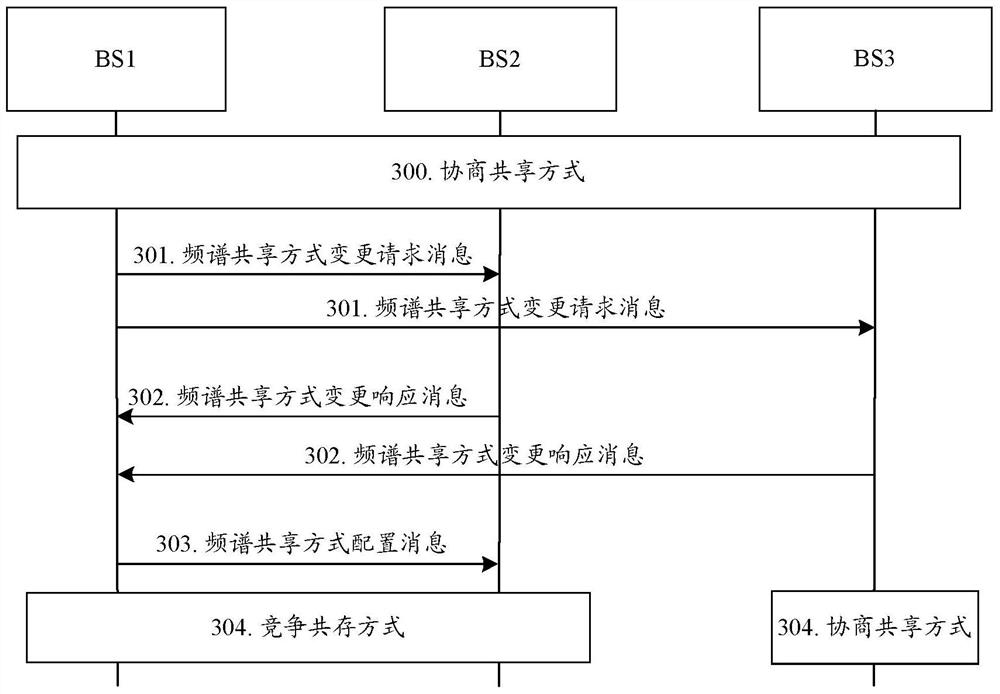
[0124] In the first embodiment, it is assumed that the communication site is base station 1 (BS1), and the relevant communication sites include BS2 and BS3; in this embodiment, it is assumed that BS1, BS2, and BS3 initially occupy the free spectrum f1 in time division through negotiation and sharing, and BS1 initiates spectrum sharing Mode Change Request. The specific process is as image 3 shown, including:

[0125] Step 300: BS1, BS2, and BS3 initially operate in a negotiation and sharing mode.

[0126] Specifically, BS1, BS2, and BS3 determine through negotiation that the time domain occupancy of frequency spectrum f1 in a unit time is as follows: Figure 4 as shown, Figure 4 It is a schematic diagram of the resource configuration before the change of the spectrum sharing method in the first embodiment of the present invention, which is repeated in the next time unit Figure 4 The time domain allocation shown. Wherein, the time domain resources indicated by the shaded...

no. 2 example

[0141] In the second embodiment, in this embodiment, it is assumed that BS1, BS2, BS3, and BS4 initially time-divisionally occupy the free spectrum f1 through negotiation and sharing, and BS1 initiates a spectrum sharing mode change request. The specific process is as Figure 6 shown, including:

[0142] Step 600: BS1, BS2, BS3, and BS4 initially operate in a negotiation and sharing mode.

[0143] Specifically, BS1, BS2, BS3, and BS4 determine through negotiation that the time domain occupancy of frequency spectrum f1 in a unit time is as follows Figure 7 as shown, Figure 7 It is a schematic diagram of the resource configuration before the change of the spectrum sharing method in the second embodiment of the present invention, which is repeated in the next time unit Figure 7 The time domain allocation shown. Wherein, the time-domain resources represented by the shaded part are the time-domain resources allocated to the corresponding BS, and in this time-domain resource ...

no. 5 example

[0186] In the fifth embodiment, it is assumed that:

[0187] The BS2 response message includes: BS2's device identifier 003, negative acknowledgment Nack;

[0188] The response message of BS3 includes: the device identifier of BS3 003, and the negative acknowledgment Nack.

[0189] That is to say, in the fifth embodiment, both BS2 and BS3 do not agree to switch to the competitive sharing mode.

[0190] Step 1003: After receiving the spectrum sharing mode change response message from BS2 and BS3, BS1 determines not to change the spectrum sharing mode, and still shares spectrum f1 with BS2 and BS3 through negotiation. ; and send spectrum sharing mode configuration messages to BS2 and BS3 respectively, to indicate that the spectrum sharing mode remains unchanged.

[0191] Step 1004: BS1, BS2, and BS3 still work in the negotiated sharing mode.

[0192] It should be noted that in this embodiment, neither BS2 nor BS3 accepts the spectrum sharing mode change request of BS1, theref...


PUM


Abstract

A spectrum sharing method is described. The method includes requesting, by the communication station, to one or more relevant communication stations to change spectrum sharing manner; determining, by the communication station, whether or not to change the spectrum sharing manner in accordance with feedback information from the relevant communication station. Using the method, fora plurality of communication stations which work at same frequency, the transition of the spectrum sharing manner is achieved by sending spectrum sharingmanner changing message to the relevant communication station by the communication station, which flexibly adapts to the needs of different coexistence environments, improves the system performance, and avoids the possible situation that the fixed pre-set spectrum sharing method cannot solve the problem of network coexistence, thereby increasing the spectrum efficiency, and further reducing increased signaling overhead and processing latency caused by invalid configuration decision.

Description

technical field [0001] The invention relates to cognitive radio technology, especially to a frequency spectrum sharing method and a communication station. Background technique [0002] With the continuous advancement of radio technology, various radio services emerge in large numbers, but the spectrum resources on which the radio services rely are limited. In the face of people's increasing demand for bandwidth, spectrum resources are extremely tight; on the other hand, under the traditional fixed spectrum allocation mode, the utilization rate of spectrum resources is not high. In a sense, it is this spectrum allocation system that is fixedly assigned to the authorized system that has caused the extremely tight situation of spectrum resources. The cognitive radio technology breaks the fixed spectrum allocation system in the traditional sense, and dynamically allocates the spectrum between systems, improving the utilization efficiency of the spectrum. In particular, as peop...

Claims


Application Information

Patent Timeline
Patent Type & Authority Patents(China)
IPC IPC(8): H04W16/14
CPCH04W16/14
Inventor 刘星郁光辉苗婷
Owner ZTE CORP
Why Eureka
Try Eureka