Ignition system and method for operating an ignition system

A technology of ignition system and operation state, applied in the field of ignition system, can solve the problem of narrow ignition voltage supply and other problems

Active Publication Date: 2016-06-22
ROBERT BOSCH GMBH
View PDF5 Cites 0 Cited by
  • Summary
  • Abstract
  • Description
  • Claims
  • Application Information

AI Technical Summary

Problems solved by technology

With current ignition systems, however, narrow limits are placed on the design of the ignition voltage supply, since the same primary voltage generator is used to supply the high voltage necessary for ignition and also to store the energy required to continue the ignition process

Method used


Image

  • Ignition system and method for operating an ignition system
  • Ignition system and method for operating an ignition system
  • Ignition system and method for operating an ignition system

Examples


Embodiment Construction

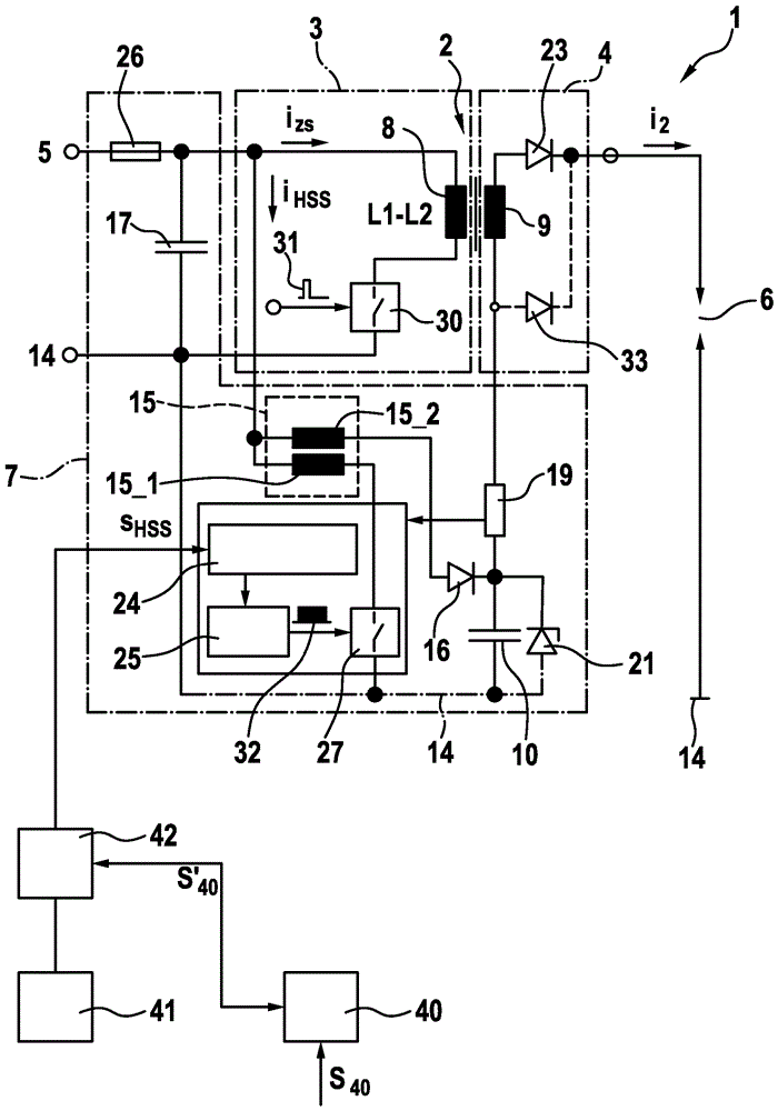
[0024] figure 1 The wiring of an ignition system 1 is shown, which includes a step-up transformer 2 as a high-voltage generator, the primary side 3 of which can be supplied with electrical energy by a power source 5 via a first switch 30 . The step-up transformer 2 formed by the primary coil 8 and the secondary coil 9 can also be referred to as a first voltage generator or a primary voltage generator. A fuse 26 is provided at the input of the line, in other words at the connection for connection to the power supply 5 . In addition, in order to stabilize the input voltage, a capacitor 17 is provided in parallel with the input end of the line or in parallel with the power supply 5 . The secondary side 4 of the step-up transformer 2 is supplied with electrical energy by inductive coupling of the primary coil 8 with the secondary coil 9 and has a device known from the prior art for performing The spark suppression diode 23 is switched on, wherein this diode can be replaced by th...


PUM


Abstract

Disclosed are an ignition system and a method for operating an ignition system for an internal combustion engine, said ignition system comprising a primary voltage generator and a step-up converter for generating an ignition spark. According to the invention, a voltage required for the ignition spark is determined, whereupon a switch-on time of the step-up converter is modified in relation to a switch-off time of the primary voltage generator.

Description

technical field [0001] The invention relates to a method for operating an ignition system for an internal combustion engine, which comprises a first voltage generator (“primary voltage generator”) and a high-voltage chopper. Furthermore, the invention relates to a corresponding ignition system. The invention relates in particular to the regulation of a high-voltage supply (Hochspannungsangebote) for generating an ignition spark by means of a step-up chopper. Background technique [0002] Ignition systems are used in the prior art to ignite an ignitable mixture in a combustion chamber of an internal combustion engine with external ignition. For this purpose, electrical energy or voltage is applied to the spark gap, in response to which an ignition spark is formed which ignites the combustible mixture in the combustion chamber. The main requirements for modern ignition systems arise indirectly from the need to reduce emissions and reduce fuel. Corresponding motorized soluti...

Claims


Application Information

Patent Timeline
Patent Type & Authority Applications(China)
IPC IPC(8): F02P3/04F02P5/15F02P9/00F02P17/12
CPCF02P3/0407F02P5/1502F02P5/1516F02P9/002F02P9/007F02P15/10F02P17/12F02P2017/121Y02T10/40
Inventor T.斯科罗内克T.帕夫拉克W.辛茨
Owner ROBERT BOSCH GMBH
Why Eureka
Try Eureka