Ignition system and method for checking electrodes of a spark plug in an internal combustion engine

A technology of ignition system and internal combustion engine, applied in the field of ignition system

Inactive Publication Date: 2017-08-18
ROBERT BOSCH GMBH
View PDF10 Cites 2 Cited by
  • Summary
  • Abstract
  • Description
  • Claims
  • Application Information

AI Technical Summary

Problems solved by technology

In particular it is not possible to introduce...

Method used


Image

  • Ignition system and method for checking electrodes of a spark plug in an internal combustion engine
  • Ignition system and method for checking electrodes of a spark plug in an internal combustion engine
  • Ignition system and method for checking electrodes of a spark plug in an internal combustion engine

Examples


Embodiment Construction

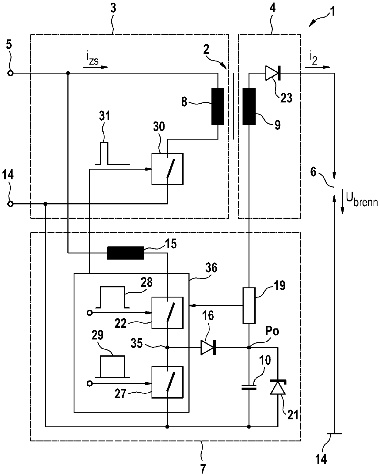
[0028] figure 1 The electrical circuit of an ignition system 1 is shown, which comprises a step-up transformer 2 as a high-voltage generator, the primary 3 of which can be supplied with electrical energy from an electrical energy source 5 via a first switch 30 . The secondary 4 of the step-up transformer 2 is supplied with electrical energy via the inductive coupling of the primary coil 8 and the secondary coil 9 and has a diode 23 known from the prior art for suppressing switch-on sparks, this diode 23 being optional Replaced by diode 21. In the mesh with secondary coil 9 and diode 23 is provided with spark gap 6 of ground wire 14, ignition current i 2 The combustible air-fuel mixture is to be ignited via this spark gap. The spark ignition voltage U, which usually fluctuates when the ignition is complete, is applied at the spark gap 6 brenn . According to the invention, a step-up converter 7 is arranged between the electrical energy source 5 and the secondary 4 of the ste...


PUM


Abstract

Disclosed are an ignition system and a method for checking electrodes of a spark gap in an ignition system for a combustion chamber of a spark ignition engine. The method comprises the following steps: generating the spark at the spark gap (6) in an operating state, without igniting a combustible mixture in the combustion chamber; determining a characteristic variable or characteristic function that represents the spark current (i2) and/or the spark voltage (Ubrenn) and/or the spark duration; comparing the characteristic variable or characteristic function with a reference value; adjusting energy for voltage build-up for spark formation and/or for maintaining an ignition spark for mixture ignition, in particular for a future ignition process, depending on the difference between the characteristic variable or the characteristic function and the reference value.

Description

technical field [0001] The invention relates to an ignition system and a method for checking an electrode of a spark gap of an ignition system for a combustion chamber of an externally ignited internal combustion engine. The invention relates in particular to the inspection of electrodes during operation of an internal combustion engine. [0002] The invention relates to an ignition system for an internal combustion engine. The invention relates in particular to ignition systems for multiple internal combustion engines, which are difficult to ignite due to (high) boost and lean mixtures ( , lean gas-stratification scheme, high AGR rate) and put forward higher requirements for this ignition system. Background technique [0003] GB717676 shows a step-up transformer for an ignition system in which a circuit part controlled by a vibrating switch of the step-up converter type is used in order to supply electrical energy to the spark generated by the step-up transformer. [00...

Claims


Application Information

Patent Timeline
IPC IPC(8): F02P9/00F02P17/12
CPCF02P17/12F02D41/009F02P3/0407F02P3/0876F02P9/002F02P9/007F02P15/10F02P2017/121F02P2017/123H01T13/60H01T15/00
Inventor T.斯科罗内克T.帕拉克W.辛兹
Owner ROBERT BOSCH GMBH
Why Eureka
Try Eureka