Magnetron sputtering cathode surface gas density distribution control device and method

A cathode surface and gas density technology, which is applied in the direction of sputtering plating, ion implantation plating, metal material coating process, etc., can solve the problems of poor film thickness uniformity, large difference, sputtering deposition rate difference, etc., to achieve gas The effect of uniform density distribution

Active Publication Date: 2016-06-29
高邮市汇金新材料科技有限公司
View PDF7 Cites 1 Cited by
  • Summary
  • Abstract
  • Description
  • Claims
  • Application Information

AI Technical Summary

Problems solved by technology

It may be due to the magnetic field at both ends of the cathode target and the uneven supply distribution of the working (reaction) gas density, which makes the sputtering deposition rate at both ends of the cathode target different from the middle part, and the closer to the two ends, the greater the difference
As a res

Method used


Image

  • Magnetron sputtering cathode surface gas density distribution control device and method
  • Magnetron sputtering cathode surface gas density distribution control device and method
  • Magnetron sputtering cathode surface gas density distribution control device and method

Examples


Example Embodiment

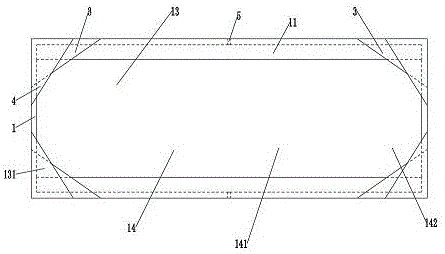
[0015] See image 3 , 4 In the shown flexible, continuous type magnetron sputtering cathode surface gas density distribution control device, the shielding cover 1 includes a panel 11 and a peripheral plate 12, and the cathode target 2 is located in the shielding cover 1. The peripheral plate 12 is provided with a working (reactive) gas injection port 5.

[0016] A rectangular hole 13 is opened on the shielding cover panel. In the four inner corners of the rectangular hole 13 on the upper part of the panel, two shielding baffles 3 and 4 are stacked one after another. The two shielding baffles 3 and 4 at each inner corner cover each Inner corner. In this way, the rectangular hole 13 removes the four inner corners 131 that are blocked by the shielding plate to form a waist-shaped sputtering hole 14. The length direction of the waist-shaped sputtering hole is consistent with the length direction of the cathode target. The two ends of the waist-shaped sputtering hole are broken line...


PUM


Abstract

The invention provides a magnetron sputtering cathode surface gas density distribution control device. Cathode surface gas density distribution can be even, and then it is guaranteed that the thickness of a coating film is basically the same in the length direction of a cathode target. The device comprises the cathode target located in a shielding cover, a kidney-shaped sputtering hole is formed in a shielding cover panel exactly facing the cathode target, the width of the middle of the kidney-shaped sputtering hole is consistent, and the widths of the two ends of the kidney-shaped sputtering hole are gradually reduced. The length direction of the kidney-shaped sputtering hole is consistent with that of the cathode target.

Description

Technical field [0001] This technology involves magnetron sputtering coating technology, specifically, it is a flexible, continuous magnetron sputtering multi-cathode deposition device cathode surface gas density distribution control technology, widely used in flexible display devices, flexible smart touch screens, flexible thin film solar The battery is being manufactured. Background technique [0002] In magnetron sputtering cathode deposition, the cathode target is located in the shielding cover. A rectangular sputtering hole is opened on the shielding cover panel facing the cathode target. The length direction of the sputtering hole is consistent with the length direction of the cathode target. When the magnetron sputtering device is working, the electrons collide with the argon gas to generate ions, and the generated ions collide with the cathode target surface under the action of an electric field to sputter target atoms. The target atoms pass through the sputtering hole an...

Claims


Application Information

Patent Timeline
IPC IPC(8): C23C14/35C23C14/54
CPCC23C14/35C23C14/54
Inventor 王鲁南朴賸一王建华全武贤李锺允窦立峰
Owner 高邮市汇金新材料科技有限公司
Why Eureka
Try Eureka