Array substrate, touch display panel, touch pressure detection method and display device
A technology of touch display panel and array substrate, which is applied in the direction of instrument, electrical digital data processing, input/output process of data processing, etc., can solve the problems of low detection accuracy and the like
- Summary
- Abstract
- Description
- Claims
- Application Information
AI Technical Summary
Problems solved by technology
Method used
Image
Examples
Embodiment 1
[0069] In this embodiment, the touch pressure can be detected by the light sensing element 30 without detecting the touch position.
[0070] Specifically, the above step S102 may include:
[0071] First, the photosensitive element 30 outputs an initial current I to the read signal lines (DL1, DL2...DLm) 1 and store. Among them, the above initial current I 1 is the current value output by the photosensitive element 30 when the user touches and does not press the touch display panel 01 .
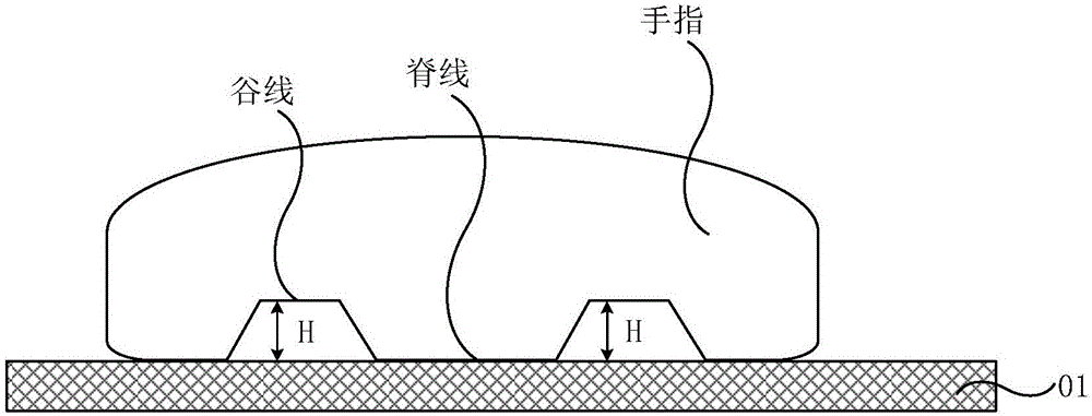
[0072] Specifically, such as Figure 5b As shown, since the ridge line is in contact with the touch display panel 01, and there is a gap H between the valley line and the touch display panel 01, it can be considered that the photosensitive element 30 in the pixel unit 21 at the position covered by the ridge line does not receive to the light, so the initial current I output by the photosensitive element 30 to the read signal line (DL1, DL2, DL3 or DL4) 1 It is represented by 0, and the ph...
Embodiment 2
[0082] In this embodiment, the touch position can be detected by the light sensing element 30, and only the touch pressure of the touch position can be detected.
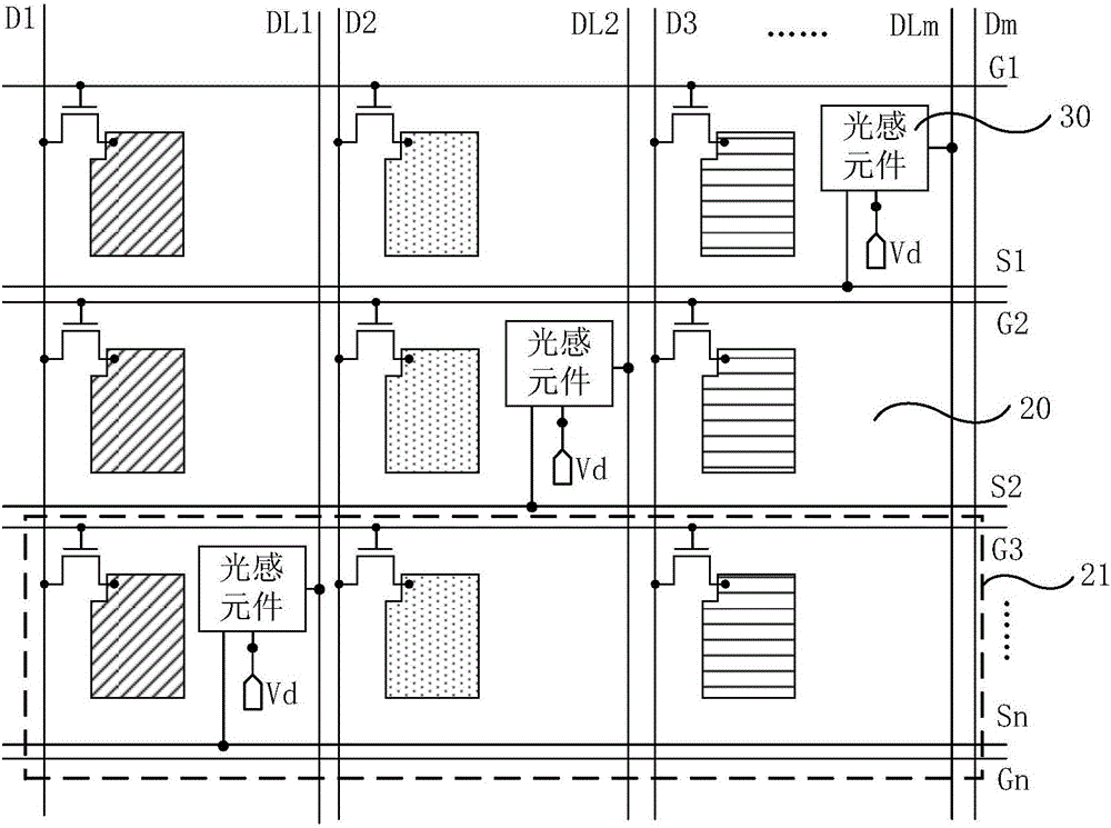
[0083] Specifically, such as Figure 4 As shown, when each pixel unit 21 is provided with a photosensitive element 30, and the photosensitive elements 30 in the same row are connected to the same scanning signal line (S1, S2... or Sn), the photosensitive elements in the same column When the same read signal line (DL1, DL2...or DLm) is connected, the current current I is output from the photosensitive element 30 to the read signal line (DL1, DL2...DLm). 2 And before storing, the above method also includes:
[0084] First, at least two rows of scanning signal lines are constituted as Figure 7 The scan signal group 40 shown, where Figure 7 One scan signal group 40 is composed of four rows of scan signal lines, and the scan signal group 40 is as Figure 9 As shown, they are turned on one by one, so that the photos...
Embodiment 3
[0091] In this embodiment, when the touch display panel 01 includes such as Figure 6a with Figure 6b In the case of the touch element 33 shown, the touch position can be detected through the touch element 33, and only the touch pressure of the touch position can be detected.
[0092] Specifically, the photosensitive element 30 outputs the current current I to the reading signal line (S1, S2...or Sn) 2 And before storing, the above method also includes:
[0093] The touch position is detected by the touch element 33 . Specifically, it can be used as Figure 6a As shown, the mutual capacitance touch capacitance can be formed by the touch sensing electrode RX and the touch driving electrode TX, or it can be adopted as Figure 6b As shown, a self-capacitive touch capacitor is formed by the touch electrodes, and the touch position is detected according to the change of the capacitance.
[0094] Next, for the initial current I 1 with current current I 2 The current change v...
PUM
 Abstract
Description
Claims
Application Information
 - R&D
- Intellectual Property
- Life Sciences
- Materials
- Tech Scout
- Unparalleled Data Quality
- Higher Quality Content
- 60% Fewer Hallucinations
Browse by: Latest US Patents, China's latest patents, Technical Efficacy Thesaurus, Application Domain, Technology Topic, Popular Technical Reports.
© 2025 PatSnap. All rights reserved.Legal|Privacy policy|Modern Slavery Act Transparency Statement|Sitemap|About US| Contact US: help@patsnap.com


