Interface switching method and switching system
A technology of interface switching and interface, which is applied in the field of man-machine interface, can solve the problems of increasing weight, not being able to adapt to the development trend of thin and light terminal equipment, increasing the cost of terminal equipment, etc., and achieve the effects of saving production cost, high recognition rate and convenient operation
- Summary
- Abstract
- Description
- Claims
- Application Information
AI Technical Summary
Problems solved by technology
Method used
Image
Examples
Embodiment 1
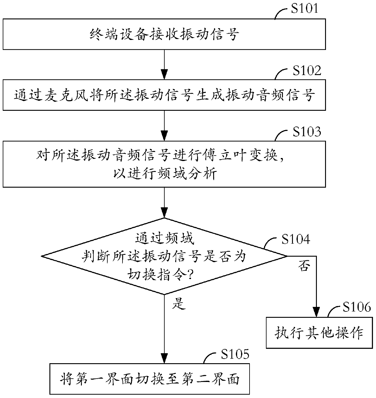
[0028] see figure 1 , which is a schematic flowchart of an interface switching method provided by an embodiment of the present invention.
[0029] The interface switching method is applied to terminal equipment, and the switching method includes:
[0030] In step S101, a vibration signal is received.
[0031] It can be understood that the vibration signal is usually generated by a tapping action, and the tapping object includes but is not limited to: tapping the display screen, casing, side of the terminal device, and external devices, such as: earphones , mobile phone case, etc. Moreover, the tapping action may be directly with a finger, or through an auxiliary object such as a stylus or a key.
[0032] In step S102, the vibration signal is generated into a vibration audio signal through a microphone.
[0033] The invention uses a microphone to identify the tapping action, and receives and records the vibration signal generated by the tapping action in a recording manner ...
Embodiment 2
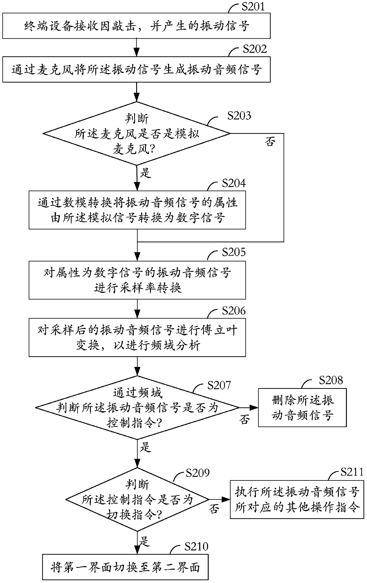
[0048] see figure 2 , which is a schematic flowchart of an interface switching method provided by an embodiment of the present invention.
[0049] The interface switching method is applied to terminal equipment, and the switching method includes:
[0050] In step S201, the terminal device receives a vibration signal generated by knocking.
[0051] It can be understood that the vibration signal is usually generated by a tapping action, and the tapping object includes but is not limited to: tapping the display screen, casing, side of the terminal device, and external devices, such as: earphones , mobile phone case, etc.
[0052] In step S202, the vibration signal is identified by a microphone to generate a vibration audio signal.
[0053] In step S203, it is judged whether the microphone is an analog microphone, wherein the attribute of the vibration audio signal generated by the analog microphone is an analog signal.
[0054] Wherein, if it is an analog microphone, execute...
Embodiment 3
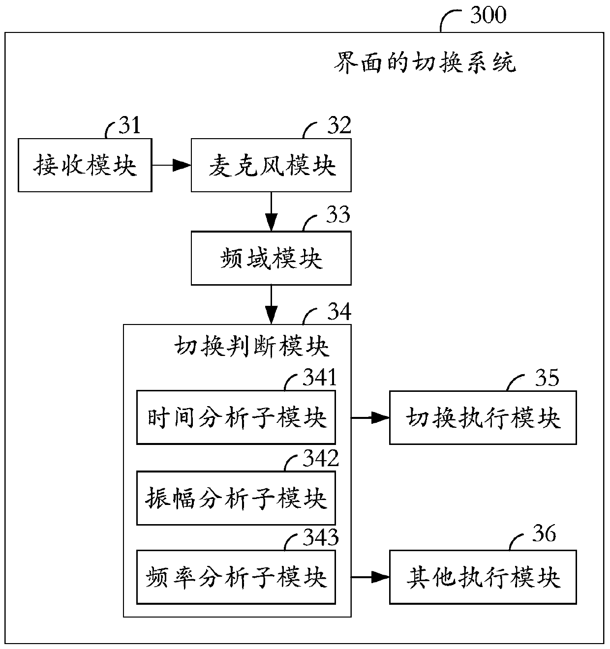
[0084] see image 3 , is a block diagram of the interface switching system provided by the embodiment of the present invention. The interface switching system is applied to a terminal device.
[0085] The interface switching system 300 includes: a receiving module 31 , a microphone module 32 , a frequency domain module 33 , a switching judgment module 34 , a switching execution module 35 , and other execution modules 36 .
[0086] Specifically, the receiving module 31 is configured to receive vibration signals.
[0087] It can be understood that the vibration signal is usually generated by a tapping action, and the tapping object includes but is not limited to: tapping the display screen, casing, side of the terminal device, and external devices, such as: earphones , mobile phone case, etc. Moreover, the tapping action may be directly with a finger, or through an auxiliary object such as a stylus or a key.
[0088] The microphone module 32 is connected to the receiving mod...
PUM
 Abstract
Description
Claims
Application Information
 - R&D
- Intellectual Property
- Life Sciences
- Materials
- Tech Scout
- Unparalleled Data Quality
- Higher Quality Content
- 60% Fewer Hallucinations
Browse by: Latest US Patents, China's latest patents, Technical Efficacy Thesaurus, Application Domain, Technology Topic, Popular Technical Reports.
© 2025 PatSnap. All rights reserved.Legal|Privacy policy|Modern Slavery Act Transparency Statement|Sitemap|About US| Contact US: help@patsnap.com


