
Subtend compression chirped pulse amplification laser system

A laser system and chirped pulse technology, applied in the laser field, can solve the problems of component damage and difficulty in improving laser performance, and achieve the effect of achieving output capability and avoiding nonlinear effects.

Active Publication Date: 2016-06-29
SHANGHAI INST OF OPTICS & FINE MECHANICS CHINESE ACAD OF SCI
View PDF3 Cites 6 Cited by
  • Summary
  • Abstract
  • Description
  • Claims
  • Application Information

AI Technical Summary

Problems solved by technology

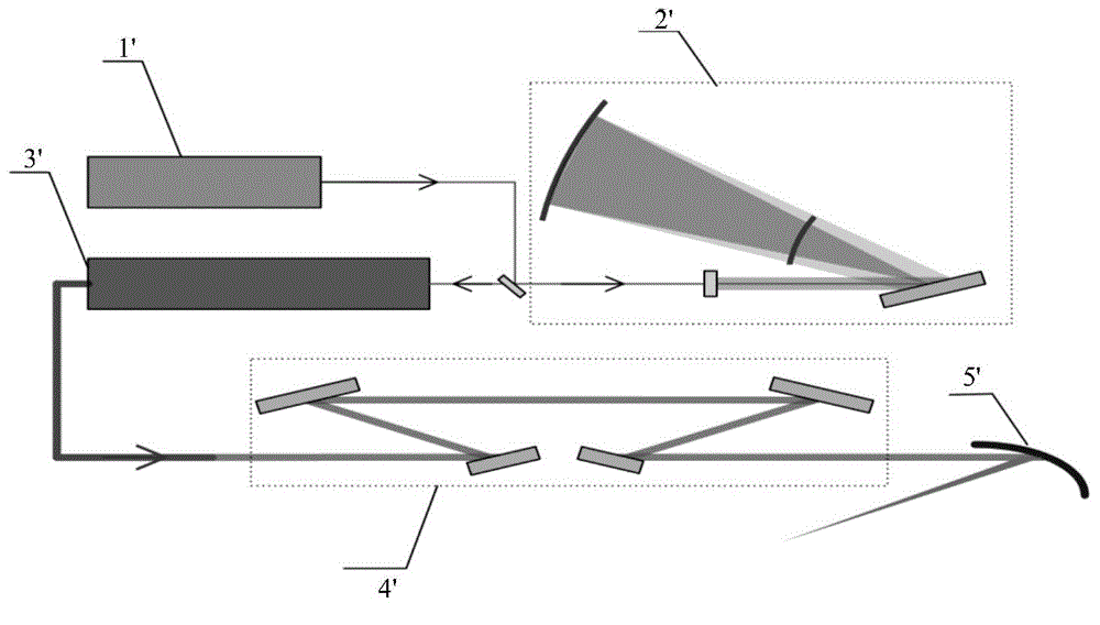
It can be seen that this technology moves the bottleneck of power improvement from the amplifier to the grating compressor. Since the grating compressor has to withstand extremely high laser power, it is easy to cause component damage
This is also the core reason why it is difficult for the above-mentioned large-scale devices to improve laser performance

Method used


Image

  • Subtend compression chirped pulse amplification laser system
  • Subtend compression chirped pulse amplification laser system
  • Subtend compression chirped pulse amplification laser system

Examples


Embodiment Construction

[0022] Below we will further elaborate on the opposing compression chirped pulse amplification laser system of the present invention in conjunction with the accompanying drawings and specific embodiments, in order to understand the structural composition and working process of the present invention more clearly, but not in terms of This limits the protection scope of the patent of the present invention.

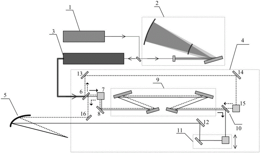
[0023] figure 2 It is a schematic diagram of the present invention's opposing compression chirped pulse amplification laser system, as can be seen from the figure, the present invention's opposing compression chirped pulse amplification laser system includes a seed source 1, a stretcher 2, an amplifier 3, an opposing compressor 4 and a focusing mirror 5 , the opposite compressor 4 includes a grating compressor 9, a first polarization splitter 6, a second polarization splitter 10, a first polarization converter 7, a second polarization converter 15, a delayer 11 and a first ...


PUM


Abstract

The invention discloses a subtend compression chirped pulse amplification laser system, comprising a seed source, a stretcher, a subtend compressor and a focusing mirror; the subtend compressor consists of a raster compressor, two polarizing beam-splitter plates, two polarization converters, one delayer and five reflectors. The subtend compression chirped pulse amplification laser system realizes the two-way time-sharing secondary utilization of the raster compressor, breaks through the limitation of the bearing capacity of the taster compressor, avoids the non-linear effect, has the identical dispersion compression amount and realizes multiplication of the output capability of the chirped pulse amplification laser system.

Description

technical field [0001] The invention relates to the field of lasers, in particular to a chirped pulse amplification laser system, which is mainly suitable for performance improvement of high-energy, high-power ultra-short and ultra-intense laser systems. Background technique [0002] At present, high-energy and high-power ultra-short and ultra-intense laser is the focus and hotspot of laser technology research in the world. The birth of chirped pulse amplification technology in 1985 made the laser power and power density available to humans break through GW (10 9 W) and 10 15 W / cm 2 , and in the following 30 years, this technology made the laser power and power density break through TW (10 12 W) and 10 18 W / cm 2 , and PW (10 15 W) and 10 20 W / cm 2 . The development of this laser technology has greatly promoted the research of basic physics, and created unprecedented conditions for human beings to explore the origin of matter, the unknown universe and energy issues. ...

Claims


Application Information

Patent Timeline
Patent Type & Authority Applications(China)
IPC IPC(8): H01S3/10G02F1/39
Inventor 李儒新李朝阳王乘李帅徐光冷雨欣徐至展
Owner SHANGHAI INST OF OPTICS & FINE MECHANICS CHINESE ACAD OF SCI
Learn More