
Specific harmonic eliminated wireless electric energy transmission system and design method

A technology of wireless power transmission and specific harmonic elimination, applied in harmonic reduction devices, AC networks to reduce harmonics/ripples, electrical components, etc., can solve problems such as poor system frequency stability

Inactive Publication Date: 2016-06-29
CHINA UNIV OF MINING & TECH
View PDF3 Cites 16 Cited by
  • Summary
  • Abstract
  • Description
  • Claims
  • Application Information

AI Technical Summary

Problems solved by technology

[0004] The purpose of the present invention is to provide a specific harmonic elimination wireless power transmission system and its design method to solve the problem that the traditional wireless power transmission system uses a resonance compensation link to form a fundamental wave channel to filter out the third and above high-order harmonic content. The problem of poor system frequency stability under load or system structure changes

Method used


Image

  • Specific harmonic eliminated wireless electric energy transmission system and design method
  • Specific harmonic eliminated wireless electric energy transmission system and design method
  • Specific harmonic eliminated wireless electric energy transmission system and design method

Examples


Embodiment 1

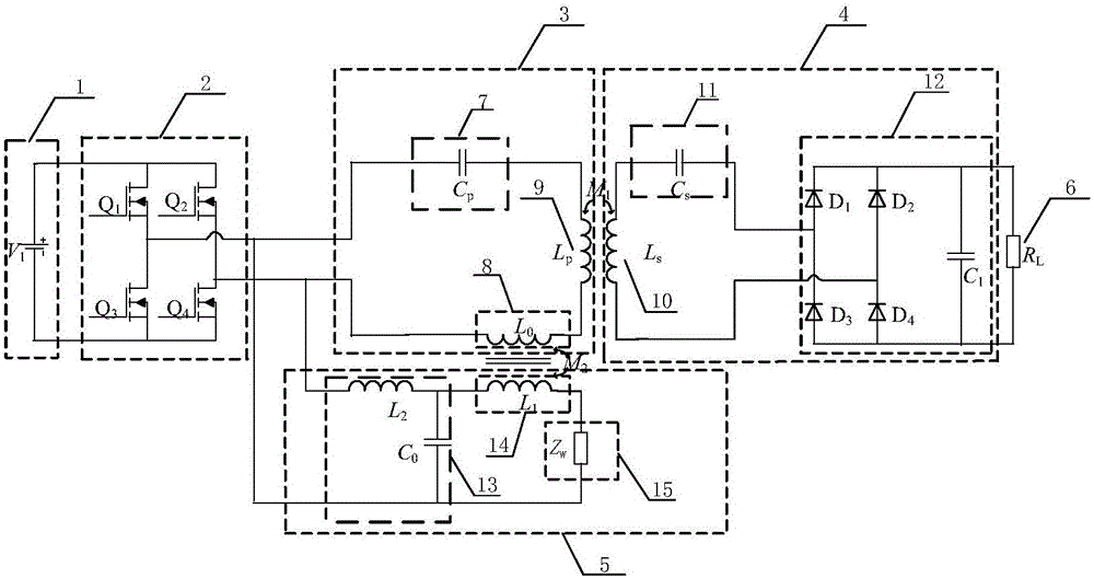
[0061] Embodiment 1: as figure 1 , a specific harmonic elimination wireless power transmission system and its design method, the system includes a DC power supply 1, a high-frequency inverter 2, a primary side energy conversion transmitting link 3, a secondary side energy receiving and transforming link 4, a primary side harmonic Energy reverse injection link 5, load 6, a total of 6 links.

[0062] Among them, the primary side energy conversion and transmitting link 3 includes the primary side resonant compensation capacitor 7, the primary side terminal 8 of the tight coupling transformer, and the primary side magnetic energy transmitting mechanism 9; the secondary side energy receiving and transforming link 4 includes the secondary side magnetic energy pick-up mechanism 10, the secondary side Resonant compensation capacitor 11 , rectification and filtering circuit 12 ; primary side harmonic energy reverse injection link 5 includes frequency selection network 13 , frequency se...


PUM


Abstract

The invention discloses a specific harmonic eliminated wireless electric energy transmission system and a design method of the specific harmonic eliminated wireless electric energy transmission system, and belongs to the wireless electric energy transmission system and design method. The system comprises a direct current power supply, a high frequency inverter, a primary side energy conversion and transmission link, a secondary side energy receiving and conversion link, a primary side harmonic energy reverse injection link and a load. After the primary side energy conversion and transmission link and the primary side harmonic energy reverse injection link respectively form a fundamental wave channel and a third harmonic extraction channel and then are reversely connected with the high frequency inverter in parallel, the third harmonic energy extracted in the primary side harmonic energy reverse injection link is reversely injected in the primary side energy conversion and transmission link through a tightly coupling transformer, thus generating superposed effects with the high frequency alternating current signals generated by the direct current power supply through the high frequency inverter. According to the system, the third harmonic content in the alternating current power supply input in the fundamental wave channel is eliminated; the design of a fundamental wave resonant network is simpler; and the system frequency stability and waveform distortion influences resulting from load or system structure change are reduced.

Description

technical field [0001] The present invention relates to a wireless power transmission system and a design method thereof, in particular to a specific harmonic elimination wireless power transmission system and a design method thereof. Background technique [0002] Traditional wired power transmission technology transmits power through the connection between conductors, but with the continuous advancement of science and technology, people have higher and higher requirements for the safety and reliability of electrical equipment, and the disadvantages of traditional contact power supply are becoming more and more serious. The more obvious, such as easy to produce wear, sparks when plugged in, and difficult to maintain. Therefore, the wireless power transmission technology based on the principle of inductive coupling arises as the times require. At present, the wireless power transmission system connects the transmitting terminal of the primary side to the high-frequency inver...

Claims


Application Information

Patent Timeline
Patent Type & Authority Applications(China)
IPC IPC(8): H02J3/01H02J50/12
CPCH02J3/01Y02E40/40
Inventor 夏晨阳王延熇雷轲王卫张杨郑凯马念朱文婷
Owner CHINA UNIV OF MINING & TECH
Learn More