
Permanent magnet torque converter

A torque converter and permanent magnet technology, applied in the direction of electrical components, electromechanical devices, electromechanical transmission devices, etc., can solve problems such as wear environment, reduce the size of the transmitted torque, and increase

Active Publication Date: 2016-06-29
NANTONG HONGDA MECHANICAL & ELECTRONIC CO LTD
View PDF6 Cites 6 Cited by
  • Summary
  • Abstract
  • Description
  • Claims
  • Application Information

AI Technical Summary

Problems solved by technology

[0002] In the mechanical transmission line, there is a need for slip transmission components, such as clutches and torque converters, etc., but dry clutches have wear and dust pollution problems in semi-linkage conditions; wet clutches and hydraulic torque converters have work The problem of liquid pollution and high cost; the current permanent magnet transmission mechanism in the market includes permanent magnet coupling, permanent magnet gear and permanent magnet eddy current transmission device, which can realize non-contact transmission and solve some problems of wear and environmental pollution, but The average speed between the input and output shafts of the permanent magnet coupling is the same, which limits its use in some occasions. The permanent magnet gear can only be driven at a fixed speed ratio. The permanent magnet eddy current transmission is large in size and is not suitable for some occasions. In use, the present invention proposes a permanent magnet arranged according to a certain rule, which can realize the working condition of the shaft coupling and the slip transmission working condition, and can change the torque when realizing the slip transmission working condition, so as to realize the driving shaft and the slave The speed difference of the moving shaft can be changed steplessly within a certain range, and the transmission torque can be increased or decreased according to the requirements

Method used


Image

  • Permanent magnet torque converter
  • Permanent magnet torque converter
  • Permanent magnet torque converter

Examples


Embodiment Construction

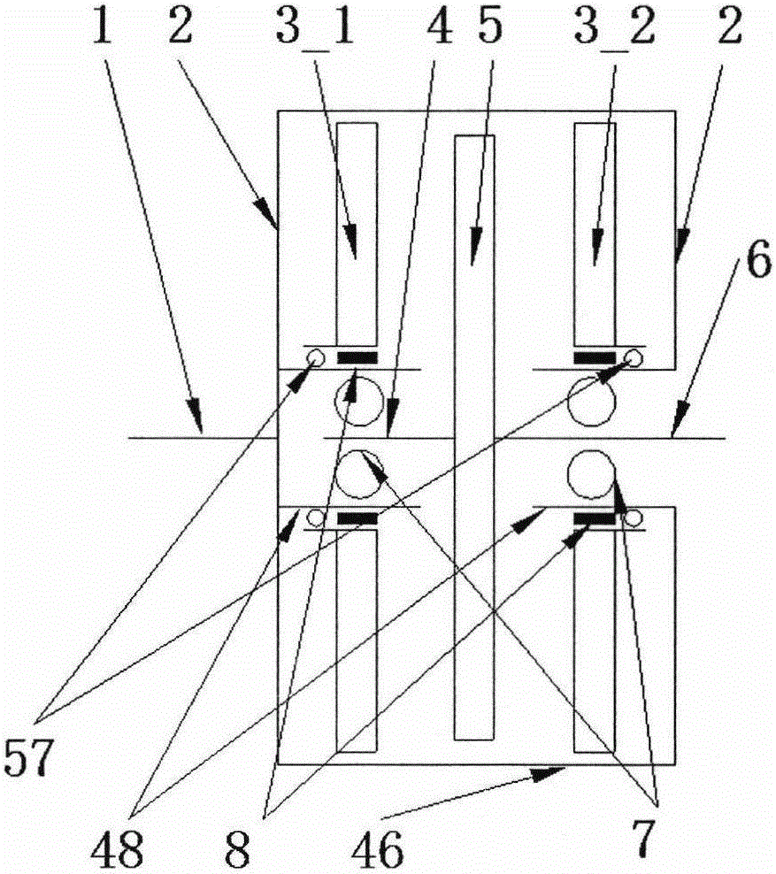
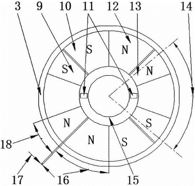
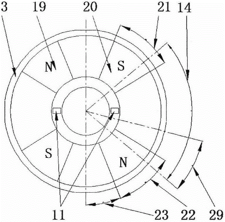
[0025] Refer to attached figure 1 - attached Figure 13, a permanent magnet torque converter is characterized in that: the input shaft 1 is coaxially connected to the disk frame 2, the diameter of the disk frame 2 is 260mm, the diameter of the complex disk 3 is 235mm, and the complex disk 3 is equipped with a positive fan-shaped main magnet 10. Forward secondary magnet 9, reverse sector-shaped main magnet 12 and reverse sector-shaped secondary magnet 13, the inner diameter of the forward sector-shaped main magnet 10 is 100 mm, the outer diameter is 220 mm, and the sector angle is 42°. Sector-shaped auxiliary magnet 9 has an inner diameter of 100mm, an outer diameter of 220mm, and a sector angle of 20°. The inner diameter of the reverse sector-shaped main magnet 12 is 100mm, an outer diameter of 220mm, and a sector angle of 42°. The reverse sector-shaped secondary magnet 13 The inner diameter is 100mm, the outer diameter is 220mm, and the sector angle is 20°. There are 8 perm...


PUM

PropertyMeasurementUnit
Sector angleaaaaaaaaaa

Abstract

The invention relates to a permanent magnet torque converter. The permanent magnet torque converter is characterized in that a coupling transmission work condition and a slip transmission work condition are achieved by permanent magnetic field force; torque can be changed in the slip transmission work condition; and the permanent magnet torque converter is suitable for various traditional vehicles, railway vehicles, new energy vehicles, electric bicycles, motorcycles, industrial and mineral machinery, ships, aircrafts and the like as a transmission component, and is especially suitable for the new energy vehicles, the traditional vehicles and the railway vehicles. The permanent magnet torque converter is characterized by structurally comprising a complicated magnetic disk, a simple magnetic disk, a magnetic disk rack, a permanent magnet, a windup spring and a bearing part; the power can be transferred according to the coupling transmission work condition and the slip transmission work condition; and the torque is changed according to the requirements in the slip transmission work condition.

Description

technical field [0001] The invention relates to a permanent magnet torque converter, which is suitable for use as a transmission part of various traditional automobiles, rail vehicles, new energy vehicles, electric bicycles, motorcycles, industrial and mining machinery, ships, aircraft, etc., especially suitable for new energy vehicles , conventional cars and rail vehicles. Background technique [0002] In the mechanical transmission line, there is a need for slip transmission components, such as clutches and torque converters, etc., but dry clutches have wear and dust pollution problems in semi-linkage conditions; wet clutches and hydraulic torque converters have work The problem of liquid pollution and high cost; the current permanent magnet transmission mechanism in the market includes permanent magnet coupling, permanent magnet gear and permanent magnet eddy current transmission device, which can realize non-contact transmission and solve some problems of wear and enviro...

Claims


Application Information

Patent Timeline
IPC IPC(8): H02K51/00
CPCH02K51/00
Inventor 邹政耀邹务丰魏婷婷
Owner NANTONG HONGDA MECHANICAL & ELECTRONIC CO LTD
Learn More