Method for simulating influence of micro vibration on image quality

A technology of image quality and micro-vibration, applied in the field of image simulation, can solve problems such as the inability to directly obtain the visual effect of micro-vibration on image quality

Active Publication Date: 2016-06-29
BEIJING INST OF SPACECRAFT SYST ENG
View PDF6 Cites 0 Cited by
  • Summary
  • Abstract
  • Description
  • Claims
  • Application Information

AI Technical Summary

Problems solved by technology

[0027] The above formula only shows the effect of camera boresight LOS shaking on the MTF of the optical system, and cannot directly visualize the effect of micro-vibration on image quality

Method used


Image

  • Method for simulating influence of micro vibration on image quality
  • Method for simulating influence of micro vibration on image quality
  • Method for simulating influence of micro vibration on image quality

Examples


Embodiment 1

[0049] The simulation method of the influence of micro-vibration on image quality, in the case of camera boresight shake caused by known micro-vibration, analyzes the boresight shake, and gives the LOS shake components of different frequencies. On this basis, according to different influence mechanisms, The redistribution and distribution of pixel energy caused by LOS shaking are given, so as to realize the purpose of simulating the influence of micro-vibration on image quality.

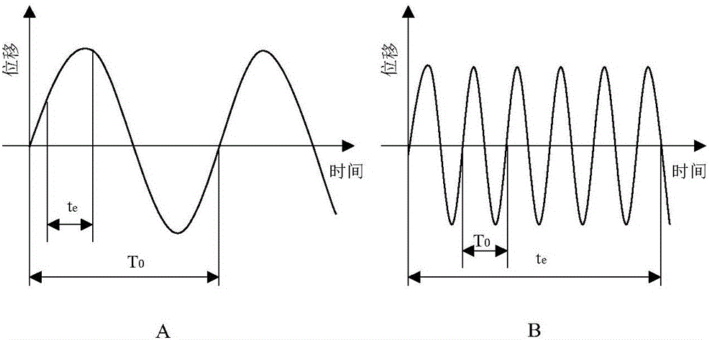
[0050] The basic principle is: currently the ground optical remote sensing cameras are mainly TDICCD cameras, and at each imaging moment (single-camera integration time), the shaking of the camera's boresight LOS will bring about two effects. One is that the energy of the ground object image caused by the large shaking is distributed to other pixels; the other is that the energy of the ground object caused by the small shaking is redistributed in adjacent pixels. These two effects generally exist at ...

Embodiment 2

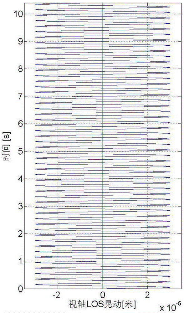
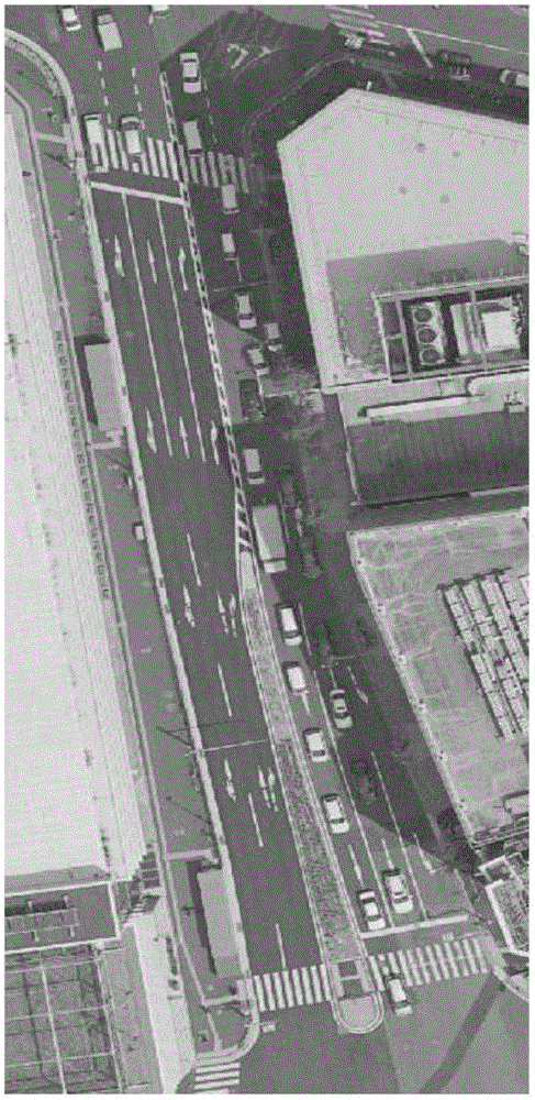
[0062] 1. First, given the LOS and the image to be simulated, enter the figure 2 with image 3 Shown:

[0063] 2. According to the aforementioned simulation process, the time needs to be registered first. Registration includes two aspects. First, the time period of LOS corresponding to each row of images needs to be registered. Secondly, it is necessary to analyze the LOS during this time period. Generally speaking, the integration time of a remote sensing satellite is 10 -4 Second order, therefore, the LOS shakes as a linear motion within this time period. Physically, at 10 -4 In the order of seconds, and in the order of 10kHz, the structural vibration is already very small. Relatively large vibrations are in the frequency band of about 0.01-100Hz. Therefore, the shaking of LOS in the single-stage integration time can be considered as linear motion from a physical analysis. The maximum value of LOS wobble within the time period that can be obtained at this time. This...


PUM


Abstract

The invention discloses a method for simulating influence of micro vibration on image quality, comprising the following steps: collecting and acquiring an in-orbit image through a TDICCD; acquiring to-be-simulated camera LOS shaking data, allocating the LOS shaking data at the moment corresponding to each row of pixels of the in-orbit image; for the in-orbit image, respectively taking a direction perpendicular to a push-broom direction and a direction along the push-broom direction as the current analysis direction, for the pixel corresponding to each moment, executing the following process: calculating a ratio of LOS shaking amplitude to pixel size; rounding down the ratio to obtain high amplitude energy of LOS shaking; translating the pixel corresponding to the current moment for a value corresponding to the high amplitude energy of the LOS shaking in the current analysis direction; subtracting the high amplitude energy of the LOS shaking from the ratio to obtain a low amplitude energy lambda of the LOS shaking; and updating an energy value of the pixel corresponding to the current moment with sum of (1-lambda) times of the energy of the pixel corresponding to the current moment before translation and lambda times of the energy of the pixel corresponding to the current moment after translation.

Description

technical field [0001] The invention belongs to the field of image simulation, and in particular relates to a method for simulating the influence of micro-vibration on image quality. Background technique [0002] Micro-vibration refers to the small amplitude of the spacecraft caused by the normal operation of the equipped equipment (such as high-speed rotating parts such as momentum wheels, stepping parts such as solar wing drive mechanisms, and swinging parts such as infrared camera swing mirrors) during the spacecraft’s orbital operation. reciprocating motion. Micro-vibration source refers to the equipment that causes micro-vibration. The micro-vibration energy is very small, compared with the strain caused by the mechanical environment of the launch section, the micro-vibration is at least one order of magnitude smaller, and will not cause structural damage. In addition to the small amplitude, the frequency range of micro-vibration is very wide, and the attitude control...

Claims


Application Information

Patent Timeline
Patent Type & Authority Applications(China)
IPC IPC(8): H04N5/232H04N17/00
CPCH04N17/002H04N23/681
Inventor 庞世伟郭倩蕊张媚李晓云朱卫红王泽宇
Owner BEIJING INST OF SPACECRAFT SYST ENG
Why Eureka
Try Eureka