Processing method for surface of workpiece using rotating cutting tool

一种切削工具、加工方法的技术,应用在用于产生装饰表面效果的工艺、制造工具、机械表面处理等方向,能够解决刀痕不足装饰花纹焕发美观等问题,达到提高美观的效果

Active Publication Date: 2016-06-29
KANEFUSA HAMONO KOUGIYOU KK
View PDF12 Cites 4 Cited by
  • Summary
  • Abstract
  • Description
  • Claims
  • Application Information

AI Technical Summary

Problems solved by technology

Since the ratio (d / W) is small in this way, the unevenness of the surface due to the knife marks is not enough, and the knife marks are not enough to look beautiful as a decorative pattern

Method used


Image

  • Processing method for surface of workpiece using rotating cutting tool
  • Processing method for surface of workpiece using rotating cutting tool
  • Processing method for surface of workpiece using rotating cutting tool

Examples


Embodiment Construction

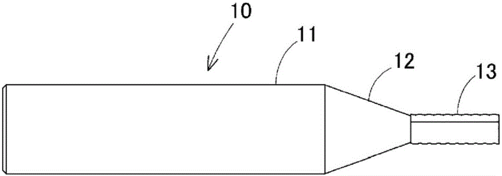
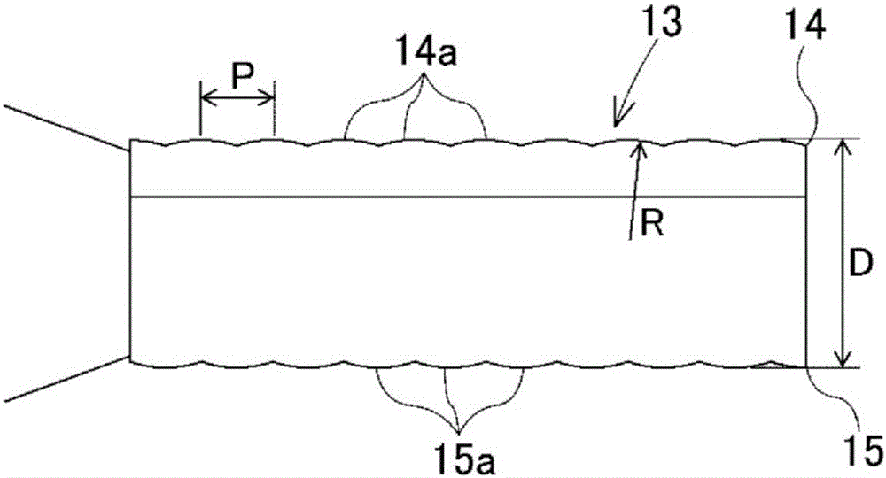
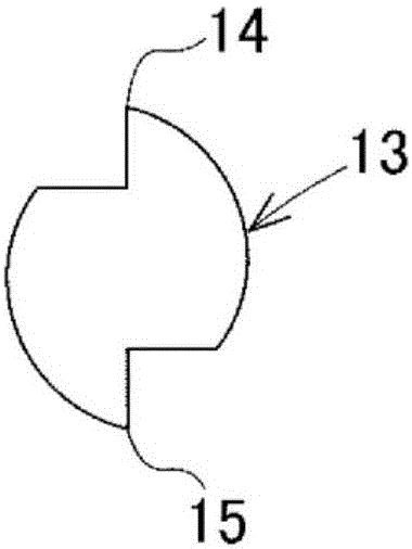
[0070] Embodiments of the present invention will be described below using the drawings. figure 1 A rotary cutting end mill (hereinafter referred to as an end mill) 10 according to Example 1 is shown in front view, Figure 2A , Figure 2B The main body 13 of the end mill 10 is shown in an enlarged front view as well as in an enlarged side view. The end mill 10 is coaxially provided with a small-diameter body 13 at the end of a large-diameter shank 11 via a connecting portion 12 , and is provided at two positions spaced apart at equal intervals in the circumferential direction of the outer periphery of the body 13 and extends in the direction of the rotation axis. A pair of cutting edges 14,15. That is, the number Z of cutting edges of the end mill 10 is two. The cutting edges 14, 15 are continuously formed with a plurality of split edges 14a, 15a at the same pitch P (same length) in the rotation axis direction. The cutting edges of the split blades 14a and 15a have an arc ...


PUM


Abstract

On the end of a large diameter shank (11), the end mill (10) is provided with a coaxial small diameter body (13) via a connecting section (12) and is provided with a pair of cutting edges (14, 15) that extend in the direction of the rotational axis at two sites that are separated at equal intervals in the circumferential direction of the circumference of the body (13). In the cutting edges (14, 15), multiple segmental edges (14a, 15a) are formed successively with the same pitch (P) (same length) in the direction of the rotational axis. The tool edges of the segmental edges (14a, 15a) have an arc shape that swells out in the radial direction with a tool edge arc diameter (R). The segmental edges (14a) are shifted by a half pitch with respect to the segmental edges (15a) in the direction of the rotational axis.

Description

technical field [0001] The present invention relates to a tool for rotating small-diameter milling cutters, end mills, etc., which are used in milling, router, etc., when manufacturing furniture parts, lighting fixtures, etc. using wood, wooden materials, resins, metals, etc. A cutting tool is a method of processing the surface of a processed material for forming a decorative pattern on the surface of the processed material. Background technique [0002] In the surface cutting process of a workpiece using a rotating cutting tool such as a milling cutter or an end mill, a trace called a tool mark occurs on the cutting surface of the workpiece due to a step difference in the boundary between the cutting edges, etc. Knife marks, thus deteriorating the quality of the machined surface. Therefore, conventionally, in surface cutting of workpieces, countermeasures have been taken exclusively to suppress interfering tool marks. In contrast, as shown in Patent Document 1, a method o...

Claims


Application Information

Patent Timeline
Patent Type & Authority Applications(China)
IPC IPC(8): B44B3/02B23C3/00
CPCB23C2210/088B27M1/003B23C5/10B44C3/06B44B3/02B44C1/222
Inventor 矢岛俊博
Owner KANEFUSA HAMONO KOUGIYOU KK
Why Eureka
Try Eureka