
Unignited plasma state detection device and unignited plasma state detection method

一种状态检测装置、等离子体的技术,应用在等离子体、放电管、电气元件等方向,能够解决RF功率放大元件元件损坏等问题

Active Publication Date: 2016-06-29
KYOSAN ELECTRIC MFG CO LTD
View PDF9 Cites 0 Cited by
  • Summary
  • Abstract
  • Description
  • Claims
  • Application Information

AI Technical Summary

Problems solved by technology

[0007] When the reflected wave generated is input to the high-frequency power supply, the RF power amplifier element of the high-frequency power supply may be damaged due to the high voltage of the reflected wave.

Method used


Image

  • Unignited plasma state detection device and unignited plasma state detection method
  • Unignited plasma state detection device and unignited plasma state detection method
  • Unignited plasma state detection device and unignited plasma state detection method

Examples


Embodiment Construction

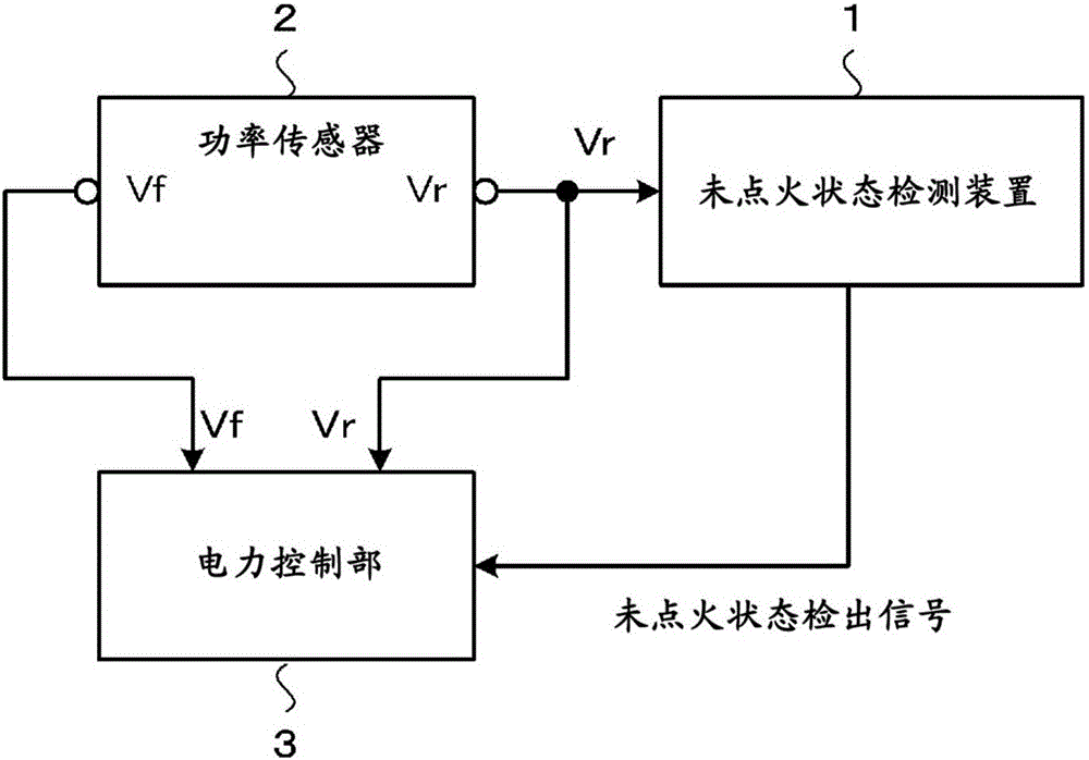
[0112] Below, while referring to the attached Figure 1 Embodiments of the present invention will be described in detail.

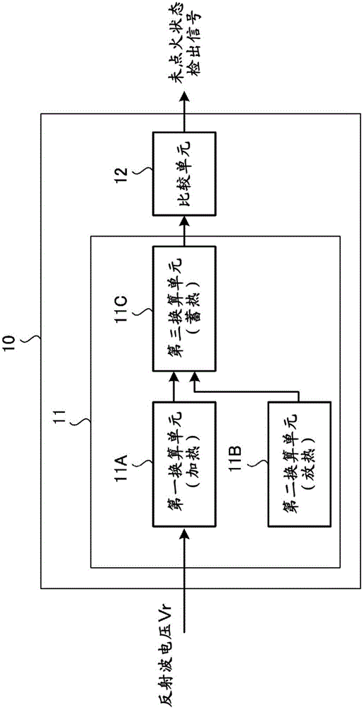
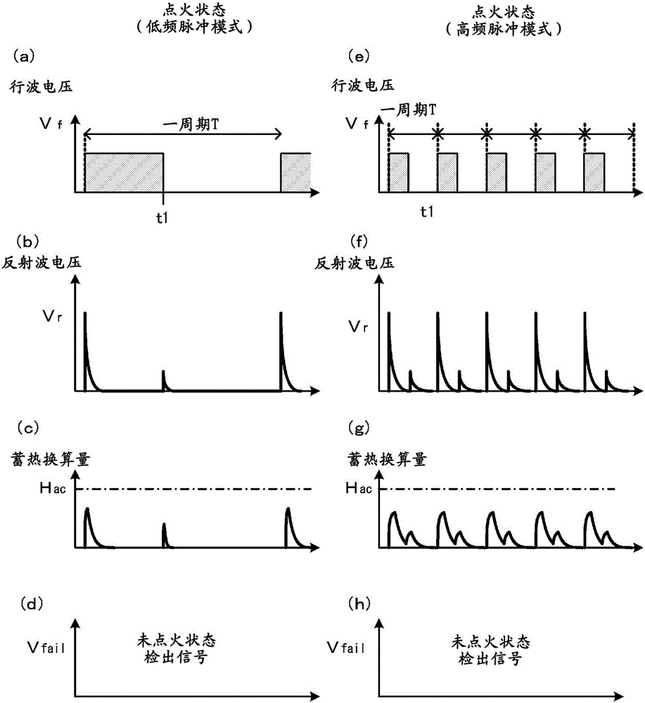
[0113] Regarding the plasma non-ignition state detection device and detection method of the present invention, below, use figure 1 Explain the connection state between the plasma non-ignition state detection device and the power sensor (powersensor), use Figure 2~4 To illustrate the schematic structure of plasma misignition state detection, use Figure 5 A flow chart illustrating the procedure for plasma misignition state detection, using Figure 6 ~ Figure 1 7 shows an aspect in which the plasma non-ignition state is detected by accumulating the voltage of the reflected wave using an analog circuit structure, using Figure 18 and Figure 19 A mode in which the plasma non-ignition state is detected by accumulating the voltage of the reflected wave with a digital circuit structure is shown. also, Figure 6 ~ Figure 1 7 shows a configuration example...


PUM


Abstract

The purpose of the present invention is, with respect to detection of the unignited state of plasma based on reflected waves, to detect unignited states during plasma anomalies while avoiding false detections during normal plasma ignition. When a pulsed output is supplied by being pulse-driven from a radio frequency power source to a plasma load, by detecting the unignited state during a plasma anomaly on the basis of a continuous state of a reflected wave, a totally reflected wave generated in the unignited state during the plasma anomaly is detected distinctly from the reflected wave generated in the normal, ignited state. This prevents a reflected wave generated in the normal, ignited state from being falsely detected as a total reflection generated in the abnormal, unignited state.

Description

technical field [0001] The present invention relates to plasma non-ignition state detection, and relates to a detection device and detection method for detecting plasma non-ignition state during plasma generation based on high-frequency power supply from a high-frequency power supply (RF power supply). Background technique [0002] It is known that plasma processing equipment such as semiconductor manufacturing equipment or electronic device manufacturing equipment, CO 2 Plasma generated by high frequency (RF) is used in plasma generators such as laser processing machines. It is known that plasma is generated by CW driving (continuous wave: non-modulated continuous wave) or pulse driving of a high-frequency power supply (RF power supply). [0003] Figure 20 It is a schematic diagram for explaining driving of a plasma load by a high-frequency power supply (RF power supply). exist Figure 20 Among them, the pulse output from the high-frequency power supply (RF power supply)...

Claims


Application Information

Patent Timeline
Patent Type & Authority Applications(China)
IPC IPC(8): H05H1/46
CPCH05H1/46H01J37/32082H01J37/32935H01J37/32174H01J37/3299H05H2242/26H05H1/4645H05H1/0012
Inventor 让原逸男相川谕大间亮介
Owner KYOSAN ELECTRIC MFG CO LTD
Learn More