Grouting pump for high-pressure constant-flow test

A constant flow, test-use technology, applied to pumps, measuring devices, fluid mixers, etc., can solve problems such as low pressure, mismatched grouting system, and failure to meet the needs of grouting tests, and achieve advanced technical parameters and prevent Precipitation effect

Active Publication Date: 2016-07-06
SHANDONG UNIV OF SCI & TECH
View PDF7 Cites 9 Cited by
  • Summary
  • Abstract
  • Description
  • Claims
  • Application Information

AI Technical Summary

Problems solved by technology

At present, there are no constant-flow grouting pumps specially used for indoor grouting simulation tests in China. The grouting model tests mostly use engineering grouting pumps. The large flow rate and high pressure cannot monitor and adjust the grouting parameters in real time, which is different from the needs of model tests. The grouting system does not match; or the injector is used as the grouting pump in the model test, the grouting rate is unstable and the pressure is low, which cannot meet the needs of high-pressure, small-flow grouting tests
The above defects severely limit the development of grouting model tests, which in turn affects the research on grouting theory

Method used


Image

  • Grouting pump for high-pressure constant-flow test
  • Grouting pump for high-pressure constant-flow test
  • Grouting pump for high-pressure constant-flow test

Examples


Embodiment Construction

[0044] The present invention will be further described below in conjunction with the accompanying drawings and embodiments.

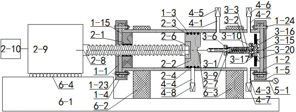
[0045] like figure 1 As shown, the grouting pump for high-pressure constant flow test consists of six parts, including high-pressure slurry storage tank, booster pressurization and flow stabilization system, built-in stirring system, slurry input / output system, monitoring system, and base. The propulsion pressurization and steady flow system extends into the high-pressure slurry storage tank, the built-in stirring system is located in the high-pressure slurry storage tank, and one end of the built-in stirring system is in contact with the propulsion pressurization and steady flow system in the high-pressure slurry storage tank, the slurry input / The output system is connected to the high-pressure slurry storage tank, the monitoring system is set on the slurry input / output system, and the high-pressure slurry storage tank and the booster pressurization a...


PUM


Abstract

The invention discloses a grouting pump for a high-pressure constant-flow test.The grouting pump comprises a high-pressure slurry storage tank, a propelling, pressurizing and flow stabilizing system, a built-in stirring system, a slurry input/output system, a monitoring system and a base.The propelling, pressurizing and flow stabilizing system extends into the high-pressure slurry storage tank.The built-in stirring system is located in the high-pressure slurry storage tank so that uniform stirring of output slurry can be achieved.One end of the built-in stirring system makes contact with the propelling, pressurizing and flow stabilizing system in the high-pressure slurry storage tank.The slurry input/output system is communicated with the high-pressure slurry storage tank.The monitoring system is arranged on the slurry input/output system.The high-pressure slurry storage tank and the propelling, pressurizing and flow stabilizing system are arranged on the base.The propelling, pressurizing and flow stabilizing system uses a stepping motor as the power source, the consistency of slurry output flow can be met, the grouting speed is adjusted by adjusting the rotating speed of the stepping motor, and dual-liquid grouting tests of different ratios can be guaranteed when multiple instruments are used at the same time.The requirements for high grouting pressure and constant grouting speed in grouting tests are met.

Description

technical field [0001] The invention relates to a grouting test device, in particular to a grouting pump for high-pressure constant flow test. Background technique [0002] The grouting model test is one of the three pillars of the grouting theory research, which plays an irreplaceable role in the study of grouting diffusion law and reinforcement mechanism. In the indoor model test, the grouting pump is responsible for the delivery of grout, which is an important part of the grouting model test. Due to the small size of the model frame, the complicated changes in the grouting process and grouting parameters, the grouting device is proposed with single and double fluid grouting, flexible adjustment of grout ratio, small and constant grouting rate, and grouting pressure. Greatly changing requirements. At present, there are no constant-flow grouting pumps specially used for indoor grouting simulation tests in China. The grouting model tests mostly use engineering grouting pum...

Claims


Application Information

Patent Timeline
Patent Type & Authority Applications(China)
IPC IPC(8): B01F5/12F04B15/02G01N33/00B01F25/60
CPCF04B15/02G01N33/00B01F25/60B01F2101/23
Inventor 张伟杰魏久传尹会永谢道雷
Owner SHANDONG UNIV OF SCI & TECH
Why Eureka
Try Eureka