
Jaw Crusher with Built-in Drive

A jaw crusher and movable jaw technology, applied in grain processing, etc., can solve the problems of large installation space, high labor intensity, and low transmission efficiency, and achieve the effects of prolonging service life, saving installation space, and reducing labor intensity

Active Publication Date: 2018-04-06
GUIZHOU WANHENG TECH DEV
View PDF6 Cites 0 Cited by
  • Summary
  • Abstract
  • Description
  • Claims
  • Application Information

AI Technical Summary

Problems solved by technology

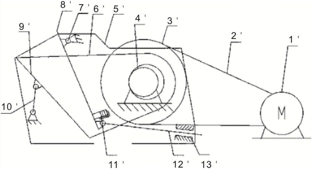
[0008] However, after a period of practical use, the arm-moving jaw low-slung crusher still has serious defects:
[0009] 1. Although an adjustment unit is provided to adjust the size of the discharge opening at the bottom of the crushing cavity; however, the adjustment is done manually, which not only has low operating efficiency, but also is labor-intensive;
[0010] 2. The motor is installed on the ground separately from the main machine. The transmission chain between the motor and the movable jaw is long, and the required installation space is large. Not only the transmission efficiency is low, but also it is easy to loosen and the belt is not easy to tension;
[0011] 3. It is impossible to quickly adjust the tightness of the transmission belt. On the one hand, it cannot adapt to the transmission needs of different materials. On the other hand, when the belt is loose, the adjustment is labor-intensive and time-consuming.
[0012] In summary, there is a lack of a jaw crusher that can mechanically adjust the size of the discharge opening at the bottom of the crushing chamber and has high transmission efficiency in the prior art.

Method used


Image

  • Jaw Crusher with Built-in Drive
  • Jaw Crusher with Built-in Drive
  • Jaw Crusher with Built-in Drive

Examples


Embodiment Construction

[0073] The technical solutions of the present invention will be clearly and completely described below in conjunction with the accompanying drawings. Apparently, the described embodiments are some of the embodiments of the present invention, but not all of them. Based on the embodiments of the present invention, all other embodiments obtained by persons of ordinary skill in the art without making creative efforts belong to the protection scope of the present invention.

[0074] In the description of the present invention, it should be noted that the terms "center", "upper", "lower", "left", "right", "vertical", "horizontal", "inner", "outer" etc. The indicated orientation or positional relationship is based on the orientation or positional relationship shown in the drawings, and is only for the convenience of describing the present invention and simplifying the description, rather than indicating or implying that the referred device or element must have a specific orientation, ...


PUM


Abstract

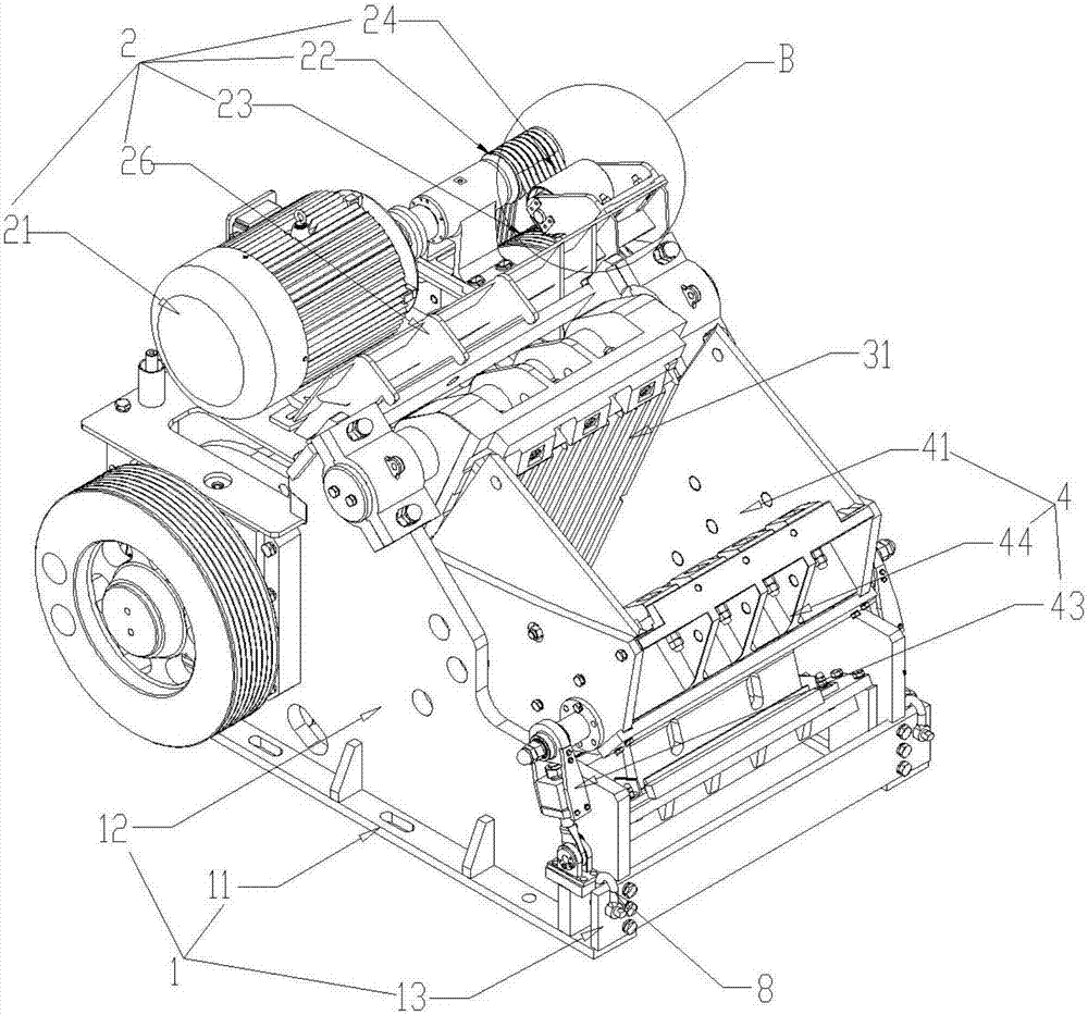
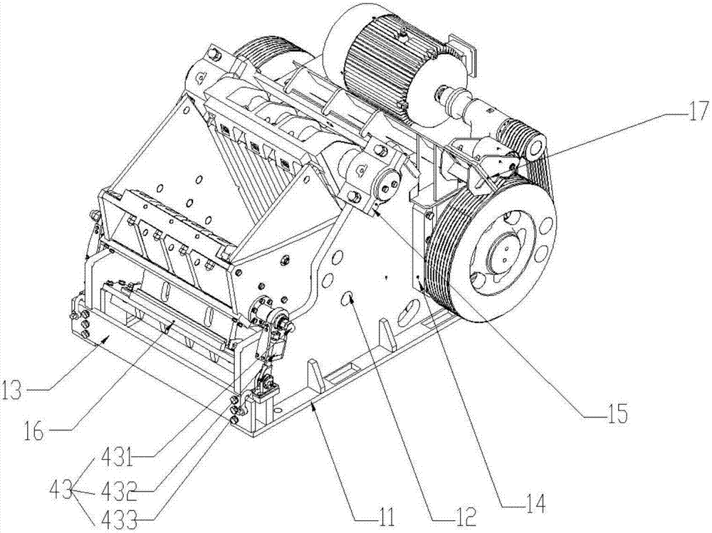
The present invention relates to the field of mining crushers. Disclosed is an internally driven jaw crusher. The jaw crusher comprises a machine frame (1), drive component (2), stationary jaw component (3), moving jaw component (4), hydraulic adjustment component (5), and adjustable stationary jaw bracket (6). The moving jaw component (4) and stationary jaw component (3) are installed on the machine frame (1). The moving jaw component (4) and stationary jaw component (3) forms a crushing chamber with a particle discharge opening at the bottom of the chamber. The drive component (2) is installed on a top portion of the machine frame (1). The drive component (2) drives a motion of the moving jaw component (4). The jaw crusher has a compact structure and requires only a small space for installation. The drive component (2) is drivingly connected to the moving jaw component (4) and drives a motion of the moving jaw component (4) relative to the stationary jaw component (3), thereby generating an oscillating change to the volume of the crushing chamber to crush a material within the crushing chamber. An output port of the hydraulic adjustment component (5) is connected to the adjustable stationary jaw bracket (6). The adjustable stationary jaw bracket (6) is connected to the stationary jaw component (3), and drives a motion of the stationary jaw component (3) relative to the machine frame (1) to change the size of the particle discharge opening of the crushing chamber. The hydraulic adjustment component (5) drives a motion of a bottom portion of the stationary jaw component (3) relative to the moving jaw component (4), thereby adjusting the size of the particle discharge opening of the crushing chamber. The invention therefore provides the advantages of easy operations, high degree of operational efficiency, and reduced labor intensity. The invention is further provided with a transmission enhancement and adjustment component (7) for adjusting a tension in a belt (23) to improve transmission efficiency.

Description

technical field [0001] The invention relates to the field of mining equipment, in particular to a built-in drive jaw crusher. Background technique [0002] The use of belt conveyors for stope materials in large-scale mines is the most efficient, largest, most economical and environmentally friendly solution, but belt conveyors are not suitable for transporting bulky materials. However, the stope crushing scheme used in coal mines has gangue or other large hard rocks that cannot be crushed, which will cause serious damage to the belt conveyor system, resulting in low efficiency, high failure rate, and high maintenance cost of the belt conveyor system. , The input-output ratio is small. [0003] Excessive volume of materials seriously affects the capacity, efficiency, and cost of the belt system, and seriously restricts the production capacity of the underground. In order to meet the demand for production capacity, it has to be increased or transported by car, which leads to ...

Claims


Application Information

Patent Timeline
Patent Type & Authority Patents(China)
IPC IPC(8): B02C1/04
CPCB02C1/04
Inventor 李绪伦皮佐武张羽林李言敖林王祯礼李绪方叶剑
Owner GUIZHOU WANHENG TECH DEV
Learn More