Magnetic floatation machine

A flotation machine and magnetic technology, applied in flotation, solid separation, etc., can solve problems affecting mineral recovery, inconvenient operation and control, and limited range of influence, so as to avoid errors, improve recovery, and reduce experimental errors. Effect

Active Publication Date: 2016-07-06
江苏三台山数据应用研究院有限公司
View PDF7 Cites 1 Cited by
  • Summary
  • Abstract
  • Description
  • Claims
  • Application Information

AI Technical Summary

Problems solved by technology

[0002] The flotation experiment of pure minerals is an important part of the theoretical research of mineral separation. Since the flotation of pure minerals in the existing laboratory is mainly carried out in small flotation cells, the corresponding operation and control are inconvenient, and the errors generated by the test are often large. Trouble disassembling the device
The existing stirring rotors extend into the flotation cell from the upper liquid surface, and the stirring is relatively unstable due to the vibration of the rotor and the stirring shaft; at the same time, the scope of influence of the rotor is limited during the scraping process, which affects the recovery rate of minerals

Method used


Image

  • Magnetic floatation machine
  • Magnetic floatation machine
  • Magnetic floatation machine

Examples


Embodiment 1

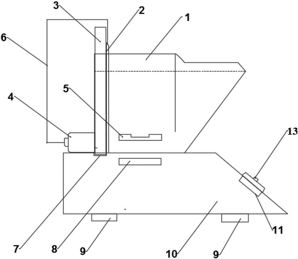
[0023] Such as figure 1 and figure 2 As shown, the present embodiment provides a magnetic flotation machine, including a flotation cell 1, a base 10, an air intake pipe 2, an air pump 4, a stirring module, a speed control module, and a temperature control module; the flotation cell 1 is arranged on The upper part of the base 10 is provided with an air intake pipe 2 inside, and the air intake pipe 2 is connected with the air pump 4 through an air conduction hose 6; The stirring mechanism in 10, the stirring mechanism includes a motor, an inner magnetic rotor 8 connected to the motor shaft; the speed control module and the temperature control module are both arranged in the base 10 .

Embodiment 2

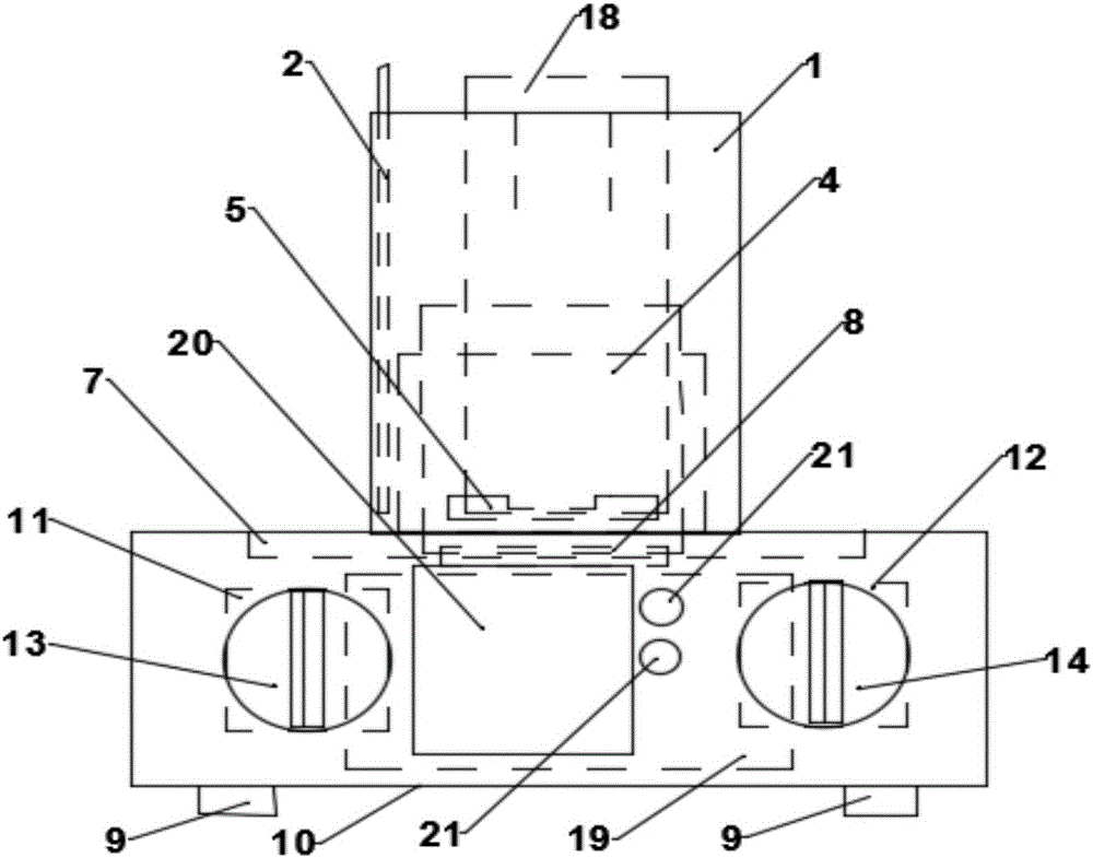
[0025] Such as figure 1 and figure 2 As shown, the embodiment provides a magnetic flotation machine. What is different from embodiment 1 is that the speed control module of the magnetic flotation machine in this embodiment includes a first resistor 11 connected to the motor and a speed adjustment knob 13; The magnetic flotation machine also includes an air charge control module, the air charge control module includes a second resistor and an air charge adjusting knob 14, and the second resistor and the air charge adjusting knob 14 are connected to an air pump through a circuit.

Embodiment 3

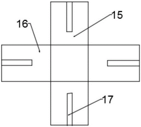
[0027] Such as Figure 1 to Figure 3 As shown, the embodiment provides a magnetic flotation machine. What is different from Embodiment 3 is that a slot is provided on the back of the flotation cell, and the fixed inserting plate is inserted into the fixed slot on the upper part of the base through the slot. The flotation cell is fixed on the base; the magnetic rotor 5 is fixedly composed of a magnetic part 15 and a nonmagnetic part 16, and a baffle 17 is designed on each corner of the magnetic stirring rotor 5; the temperature control module includes a line connection The temperature adjustment plate 18, the temperature control device 19, the temperature display screen 20 and the temperature setting button 21; the temperature adjustment plate 18 is composed of a heat dissipation plate 22 with a heating wire, a heat insulating material 23, a temperature probe 24, and a fixed spring 25. The temperature regulating plate is fixed on the inner wall of the flotation cell 1 by two fi...


PUM


Abstract

The invention provides a magnetic floatation machine, comprising a flotation tank, a base, an intake pipe, a pneumatic pump, a stirring module, a rotation speed control module, and a temperature control module; the floatation module is disposed on the upper portion of the base, the intake pipe is disposed inside the flotation tank, and the intake pipe is connected with the pneumatic pump through a guide hose; the stirring module comprises a magnetic rotor disposed at the bottom of the flotation tank and a stirring mechanism disposed in the base, and the stirring mechanism comprises a motor and an inner magnetic rotor connected with a shaft of the motor; both the rotation speed control module and the temperature control module are disposed in the base. The magnetic flotation machine of the invention has enlarged flotation skimming area and improved stability of pulp level, helps mineral pressing test workers to make better test studies on pure mineral flotation and better reduces the test error.

Description

technical field [0001] The invention relates to the field of mineral processing engineering, in particular to a magnetic flotation machine used for flotation experiments. Background technique [0002] The flotation experiment of pure minerals is an important part of the theoretical research of mineral separation. Since the flotation of pure minerals in the existing laboratory is mainly carried out in small flotation cells, the corresponding operation and control are inconvenient, and the errors generated by the test are often large. Device disassembly is troublesome. The existing stirring rotors extend into the flotation cell from the upper liquid surface, and the stirring is relatively unstable due to the vibration of the rotor and the stirring shaft; at the same time, the scraping process is limited by the influence range of the rotor, which affects the mineral recovery rate. Therefore, it is urgent to develop and design a kind of magnetic drive flotation machine mainly u...

Claims


Application Information

Patent Timeline
IPC IPC(8): B03D1/14
CPCB03D1/14
Inventor 赵敏捷党泽清赵敏耀王佳信
Owner 江苏三台山数据应用研究院有限公司
Why Eureka
Try Eureka