Upward flanging device for stamped pieces

A technology of stamping parts and components, which is applied in the field of flanging devices, can solve problems such as insufficient upturning force, insufficient installation surface area, and inability to install upturning inserts, etc., and achieves the effect of reasonable structural layout

Active Publication Date: 2016-07-06
ANHUI JIANGHUAI AUTOMOBILE GRP CORP LTD
View PDF9 Cites 2 Cited by
  • Summary
  • Abstract
  • Description
  • Claims
  • Application Information

AI Technical Summary

Problems solved by technology

[0005] The purpose of the present invention is to provide a stamping parts upturning device to solve the deficiencies in the prior art. The problem that the entire insert cannot be installed when it is large, applies to both small stampings and large stampings

Method used


Image

  • Upward flanging device for stamped pieces
  • Upward flanging device for stamped pieces
  • Upward flanging device for stamped pieces

Examples


Embodiment 2

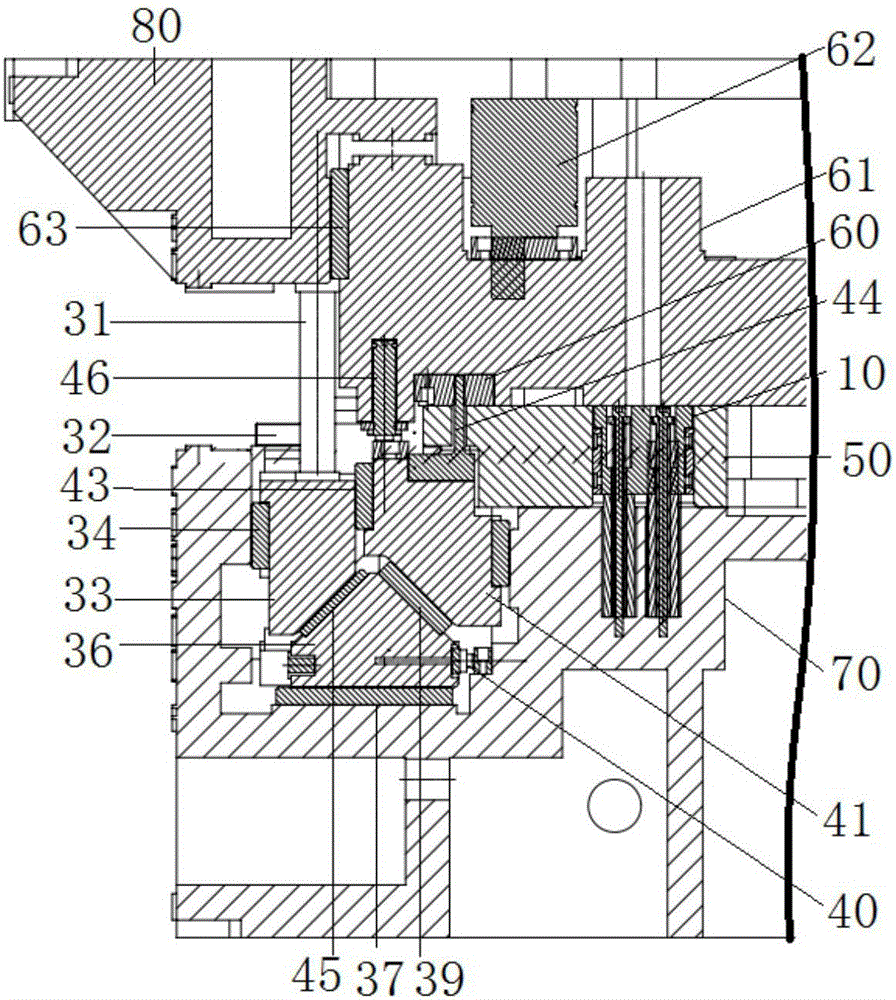
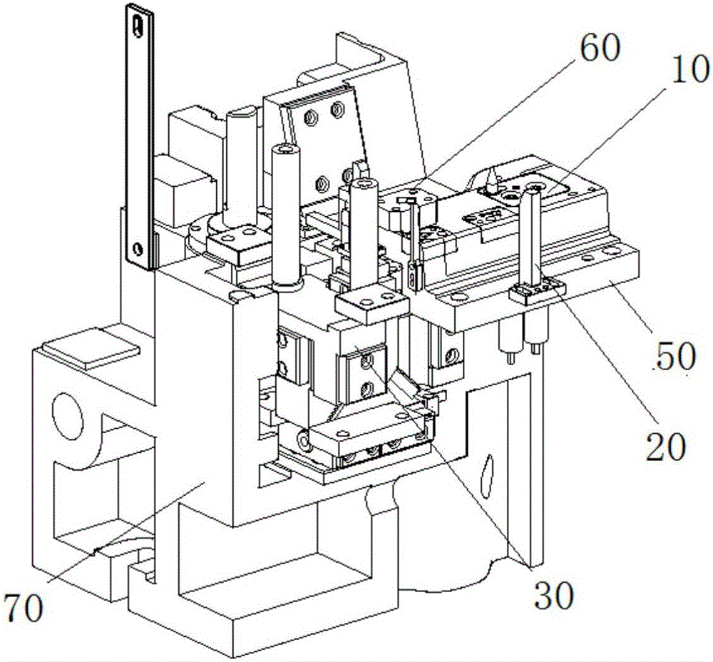
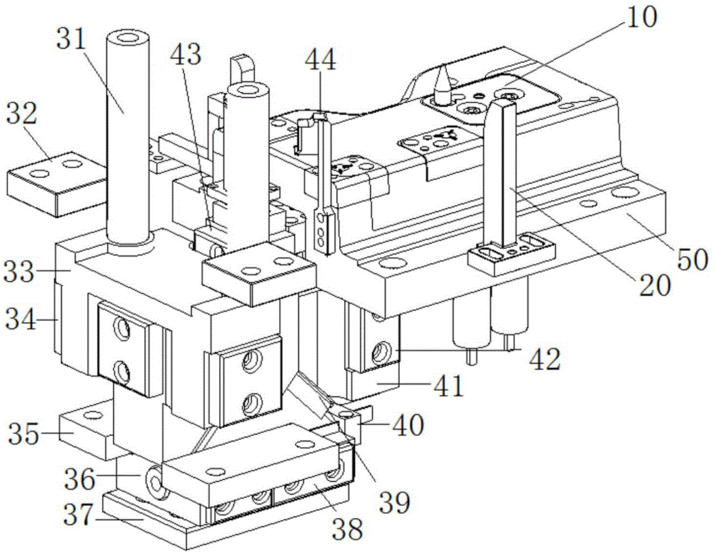
[0028] Embodiment 2 of the present invention: as Figure 1-Figure 4 As shown, a stamping part upper flanging device includes an upper mold base 80, a lower mold base 70, a pressing core body 61, an upturning mechanism 30 and a punch 50, and the pressing core body 61 is passed through a nitrogen cylinder The assembly 62 and the binder core guide element 63 are installed on the upper mold base 80, and the binder core guide element 63 is vertically arranged between the binder core body 61 and the upper mold base 80, Play the role of sliding. The turning-up mechanism 30 and the punch 50 are fixedly installed on the lower mold base 70, the turning-up mechanism 30 includes a drive slider 33, a pulley slider 36 and an upturning slider 41, and the slider slide The top of block 36 is the cone that section shape is triangular, and the bottom is cuboid, and the bottom of described driving slide block 33 and described turning over slide block 41 is all provided with the inclined-plane th...


PUM


Abstract

The invention discloses an upward flanging device for stamped pieces. The upward flanging device comprises an upper die seat, a lower die seat, a material pressing core body, an upward flanging mechanism and a convex die, wherein the material pressing core body is mounted on the upper die seat through a material pressing nitrogen cylinder assembly and a material pressing core guide element; the upward flanging mechanism and the convex die are fixedly mounted on the lower die seat; the upward flanging mechanism comprises a driving sliding block, a tackle sliding block and an upward flanging sliding block; the upper part of the tackle sliding block is a cone body with a triangular section, and the lower part of the tackle sliding block is a cuboid; slopes matched with the upper part of the tackle sliding block are arranged at the lower parts of the driving sliding block and the upward flanging sliding block; a driving rod is arranged at the top of the driving sliding block; an upward flanging insert and a balance nitrogen cylinder assembly are arranged at the top of the upward flanging sliding block. The upward flanging device can provide high material pressing force, and the problems of insufficient mounting area, insufficient upward flanging power and failure in mounting a large upward flanging insert are solved; the upward flanging device is suitable for both small-size and large-size stamped parts.

Description

technical field [0001] The invention relates to a flanging device, in particular to a flanging device for stamping parts. Background technique [0002] In the development of complete automobiles, many stamping parts have an upturned edge (upper flanging) shape in order to realize the overlap or shape of the parts. Now it is generally realized by the standard reverse wedge in the stamping die, but due to the existing The standard reverse wedge provides less force, and is generally suitable for small flanging. For some complex shapes, if the existing reverse wedge is used, there will be insufficient mounting surface area and insufficient flanging driving force. [0003] For example, the Chinese utility model patent specification with application number 201420219823.9 discloses a wedge mechanism for turning holes upwards. The guide block has two cone structures, and the transmission rod is provided with inclined surfaces opposite to the two cone surfaces. The guide block moves...

Claims


Application Information

Patent Timeline
IPC IPC(8): B21D19/02B21D37/10B21D43/00B21D45/04
CPCB21D19/02B21D37/10B21D43/003B21D45/04
Inventor 何鹏申陈世涛徐肖李昂
Owner ANHUI JIANGHUAI AUTOMOBILE GRP CORP LTD
Why Eureka
Try Eureka