Tensioning clamp for sheet-type part subjected to rotary milling processing

A kind of rotary milling and thin plate technology, applied in metal processing machinery parts, manufacturing tools, metal processing equipment and other directions, can solve the problems of clamping and deformed parts stiffness, etc., to improve clamping stiffness, prolong tool life and reduce processing costs. Effect

Active Publication Date: 2016-07-06
NORTHWESTERN POLYTECHNICAL UNIV
View PDF6 Cites 7 Cited by
  • Summary
  • Abstract
  • Description
  • Claims
  • Application Information

AI Technical Summary

Problems solved by technology

[0004] Aiming at the problems of clamping deformation and low rigidity of the existing thin-plate rotary milling parts during processing, the present invention proposes a fixture suitable for clamping and positioning of all thin-plate rotary milling parts. It can effectively improve the clamping stiffness of thin plate parts, thereby improving the machining accuracy of parts

Method used


Image

  • Tensioning clamp for sheet-type part subjected to rotary milling processing
  • Tensioning clamp for sheet-type part subjected to rotary milling processing
  • Tensioning clamp for sheet-type part subjected to rotary milling processing

Examples


Embodiment Construction

[0037] Embodiments of the present invention are described in detail below, examples of which are shown in the drawings, wherein the same or similar reference numerals designate the same or similar elements or elements having the same or similar functions throughout. The embodiments described below by referring to the figures are exemplary and are intended to explain the present invention and should not be construed as limiting the present invention.

[0038] In describing the present invention, it should be understood that the terms "center", "longitudinal", "transverse", "length", "width", "thickness", "upper", "lower", "front", " Orientation indicated by rear, left, right, vertical, horizontal, top, bottom, inside, outside, clockwise, counterclockwise, etc. The positional relationship is based on the orientation or positional relationship shown in the drawings, which is only for the convenience of describing the present invention and simplifying the description, rather than ...


PUM


Abstract

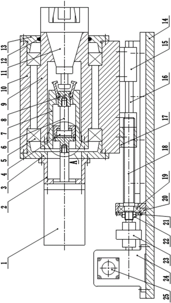
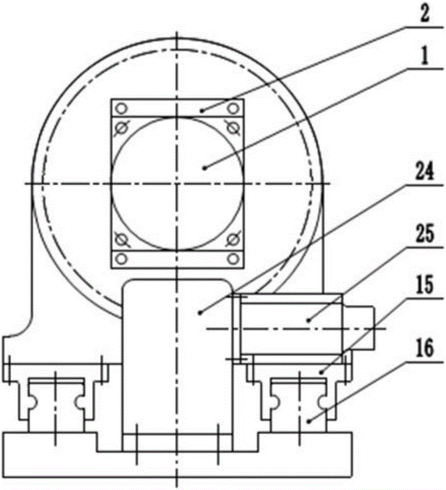
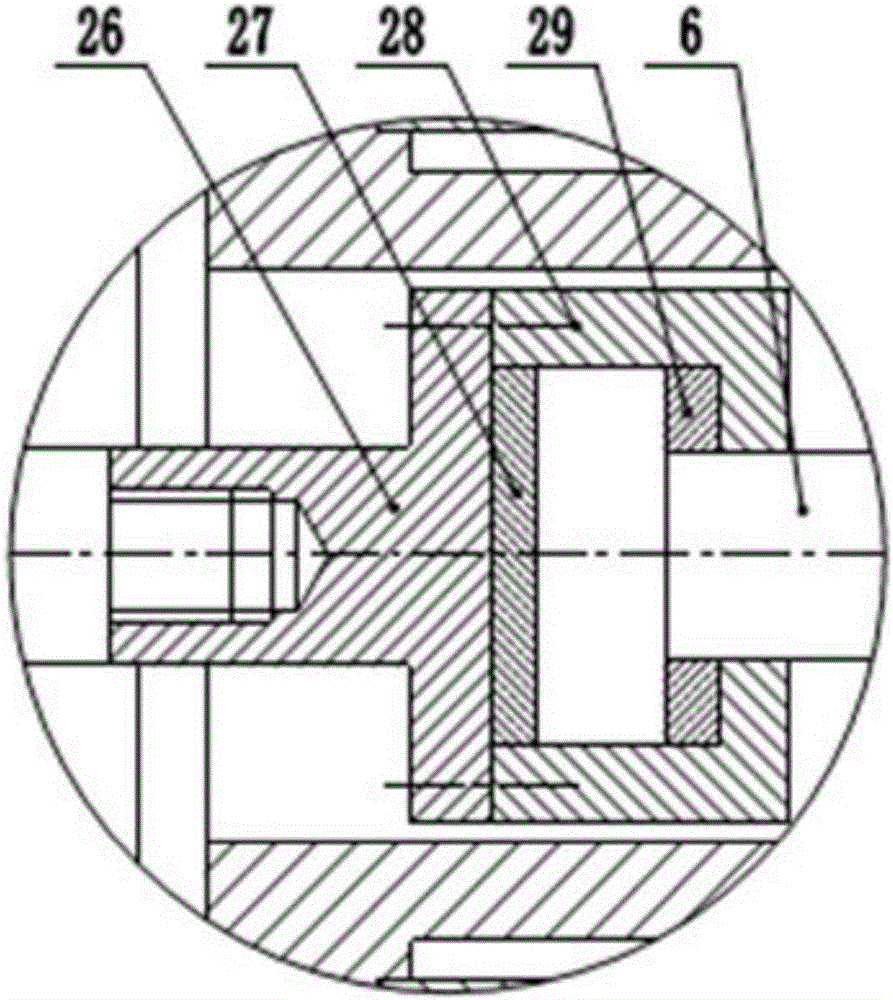
The invention provides a tensioning clamp for a sheet-type part subjected to rotary milling processing. The tensioning clamp for the sheet-type part subjected to the rotary milling processing consists of a pedestal, a tensioning component and a clamping component, wherein the clamping component comprises a clamping driving device, a box body, a rotary shaft, a retainer cup, a movement crossover joint, a connecting rod, a pulling claw and a symmetrical clamping head; the tensioning component comprises a tensioning driving device, a transmission device and a guide rail sliding block device. According to the tensioning clamp for the sheet-type part subjected to the rotary milling processing, the sheet-type part is fixed by adopting a tensioning way; the clamping rigidity of the part can be effectively improved; the cutter relieving deformation in the processing process of the part is reduced; the processing vibration is restrained; the processing quality of the part is improved; the service life of a knife tool is prolonged; therefore, the processing cost is decreased; tensioning force is controlled through the tensioning driving device; the tensioning force can be guaranteed to be uniform and can be further regulated according to requirement; the symmetrical clamping head is tensioned to clamp the part through the clamping driving device; the rotary center of the part can be guaranteed to be unchangeable in a clamping process; the clamping deformation cannot be caused; further, the operation is simple; a clamping error caused by a human factor can be avoided.

Description

technical field [0001] The invention relates to the technical field of mechanical processing, in particular to a tensioning fixture used for thin plate rotary milling parts. Background technique [0002] With the development of industrial technology, more and more products with complex surfaces are designed and used, coupled with the requirements of lightweight design of products, the design and use of thin plate parts are increasing, especially in the aerospace field. Thin-plate parts with complex curved surfaces (such as compressor blades, turbine blades, etc.) are usually milled by multi-axis machining centers. However, due to the inherent weak rigidity of thin-plate parts, the machining vibration increases and the tool wears faster. The processing efficiency is low. [0003] Multi-axis processing of thin plate parts usually adopts the method of tailstock top support. However, this method relies on workers to manually control the clamping force. In recent years, related...

Claims


Application Information

Patent Timeline
Patent Type & Authority Applications(China)
IPC IPC(8): B23Q3/06
CPCB23Q3/065
Inventor 罗明张仲玺张定华吴宝海李涛姚懿航高建
Owner NORTHWESTERN POLYTECHNICAL UNIV
Why Eureka
Try Eureka