
Vacuum absorbing and grabbing mechanism for optical elements and control method thereof

A technology of optical components and grasping mechanisms, which is applied in the direction of manipulators, manufacturing tools, chucks, etc., and can solve problems such as low cleanliness, poor safety and reliability, and damage to optical components

Inactive Publication Date: 2016-07-06
LASER FUSION RES CENT CHINA ACAD OF ENG PHYSICS
View PDF7 Cites 11 Cited by
  • Summary
  • Abstract
  • Description
  • Claims
  • Application Information

AI Technical Summary

Problems solved by technology

Since these optical components are getting bigger and bigger in diameter and heavier in weight, and the next generation of high-energy solid-state laser devices in the future will require a larger number of large-caliber and heavy-weight optical components, my country currently uses the method of manually assembling large-caliber optical-mechanical units. Low cleanliness, poor safety and reliability, high labor intensity and low production efficiency can no longer meet the assembly requirements of a large number of large-diameter and heavy-weight optical components, so there is an urgent need for automated equipment to complete the clean and precise assembly of large-diameter optical components
[0003] During the installation and use of large-aperture optical components, it is often necessary to adjust their position and posture. Considering the high cleanliness requirements of large-aperture optical components, it is usually only allowed to touch the area within 20mm of the rectangular frame around the optical component. When picking, it is easy to cause damage to the optical element, and there is a risk of contamination. Therefore, it is difficult to meet the grasping requirements of large-diameter optical elements
[0004] The invention relates to the assembly of optical elements in high-energy solid-state laser devices. The optical elements include reflectors, which are mainly used to install the optical elements into the optical element mounting frame. The optical element mounting frame is usually placed vertically and is not easy to assemble. Optical components are usually cuboid, larger in size, heavier in weight, higher in precision, and quite expensive. If manual assembly is used, the labor intensity of workers will be high and the optical components will be easily damaged.

Method used


Image

  • Vacuum absorbing and grabbing mechanism for optical elements and control method thereof
  • Vacuum absorbing and grabbing mechanism for optical elements and control method thereof
  • Vacuum absorbing and grabbing mechanism for optical elements and control method thereof

Examples


Embodiment Construction

[0058] The present invention will be described in further detail below in conjunction with the accompanying drawings and specific embodiments.

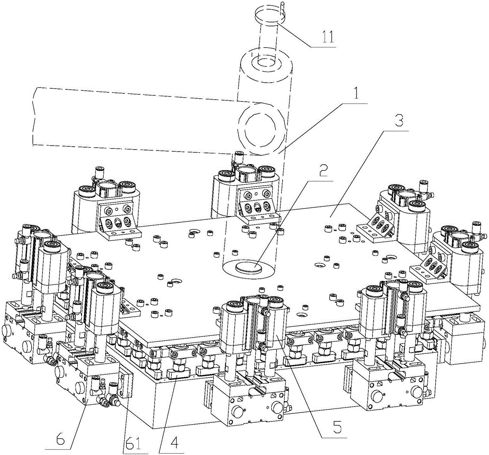
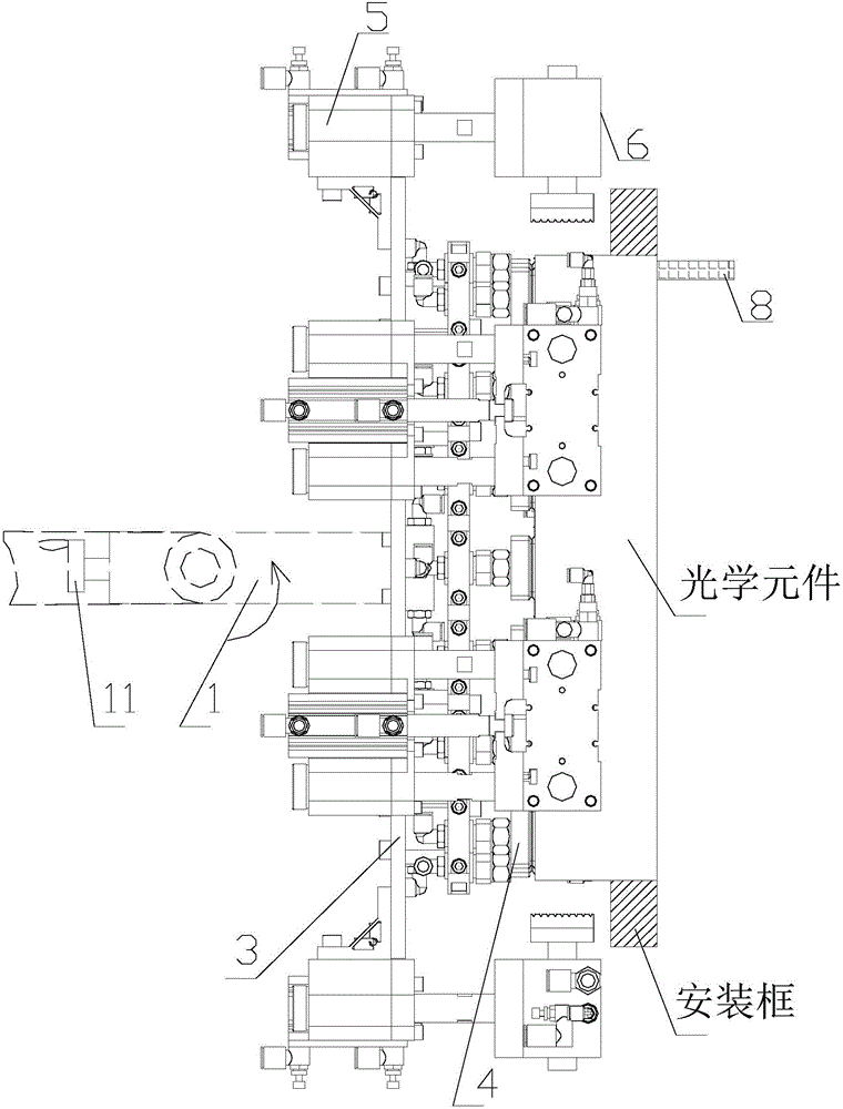
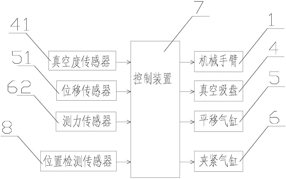
[0059] Such as figure 1 , figure 2 with image 3 As shown, a vacuum adsorption and grasping mechanism for optical components includes a mechanical arm 1, and also includes a manipulator flange 2, a fixed plate 3, a vacuum suction cup 4, a translation cylinder 5, and a clamping cylinder 6;

[0060] The manipulator 1 is connected to the upper surface of the fixed plate 3 through the manipulator flange 2;

[0061] A plurality of vacuum suction cups 4 are evenly distributed along the edge line on the lower surface of the fixed disk 3, and each vacuum suction cup 4 faces downward for absorbing optical components to be grasped;

[0062] The side walls around the fixed plate 3 are fixedly connected with at least two translation cylinders 5; the piston rods of the translation cylinders 5 are vertically arranged, and a clamping cylinder 6 ...


PUM


Abstract

The invention discloses a vacuum absorbing and grabbing mechanism for optical elements and a control method thereof. The mechanism comprises a mechanical arm; the mechanical arm is connected to the upper surface of a fixed disc through a manipulator flange plate; multiple downward vacuum suckers are uniformly distributed on the lower surface of the fixed disc along the edge line for absorbing the optical elements to be grabbed; at least two translation cylinders are fixedly connected to the peripheral side wall of the fixed disc; the translation cylinders are longitudinally arranged; a piston rod of each translation cylinder is connected with a clamping cylinder; piston rods of the clamping cylinders are horizontally arranged towards the side surfaces of the optical elements; the translation cylinders drive the clamping cylinders to longitudinally move; the clamping cylinders laterally clamp the optical elements; and the mechanical arm, the vacuum suckers, the translation cylinders and the clamping cylinders are all connected to a control device. The mechanism can firmly grab the optical elements and gradually and stably mount the optical elements in an optical element mounting frame, is fast and convenient, and cannot damage the optical elements.

Description

technical field [0001] The invention relates to the field of high-energy solid-state laser devices, in particular to a vacuum adsorption and gripping mechanism for optical elements and a control method thereof. Background technique [0002] A high-energy solid-state laser device includes thousands of optical-mechanical units with independent functions and tens of thousands of various precision optical components. The safe and reliable operation of the device requires these large-caliber optical components to be installed with high precision and high cleanliness. Since these optical components are getting bigger and bigger in diameter and heavier in weight, and the next generation of high-energy solid-state laser devices in the future will require a larger number of large-caliber and heavy-weight optical components, my country currently uses the method of manually assembling large-caliber optical-mechanical units. Low cleanliness, poor safety and reliability, high labor intens...

Claims


Application Information

Patent Timeline
Patent Type & Authority Applications(China)
IPC IPC(8): B25J15/06
CPCB25J15/0616
Inventor 裴国庆王辉徐旭周海熊召叶朗严寒独伟峰李珂
Owner LASER FUSION RES CENT CHINA ACAD OF ENG PHYSICS
Learn More