Relief molding process and device as well as relief product

A molding device, technology of molding process, applied in the direction of lamination device, synthetic resin layered product, process for producing decorative surface effect, etc., can solve waste, cannot achieve the accuracy of relief image by applying pressure, and cannot press out relief pattern And other issues

Active Publication Date: 2016-07-06
罗实
View PDF7 Cites 3 Cited by
  • Summary
  • Abstract
  • Description
  • Claims
  • Application Information

AI Technical Summary

Problems solved by technology

[0004] Due to the poor plasticity of leather and PVC sheets, the embossment must be pressed with a concave-convex mold, but the embossed pattern is fuzzy, and it is impossible to press out a fine relief pattern, and making the concave-convex mold at the same time increases the production cost
Moreover, the fineness of the relief pattern is directly related to the pressure of the hydraulic press. The greater the pressure of the hydraulic press, the finer the pattern will be, and the smaller the pressure of the hydraulic press, the more blurred the relief pattern will be. However, leather and PVC sheets can withstand The pressure is limited. If the pressure is too large, it will easily cause damage to the leather and PVC sheet, resulting in unnecessary waste. If the pressure is too small, it will not be able to meet the requirements of the accuracy of the relief image.
In addition, natural cooling is required after the embossed products are pressed, and the cooling time is long, which reduces the production efficiency of the embossed products
In addition, after the three-dimensional relief pattern is pressed, polishing and other processes are required to show the color depth of the relief pattern. The polishing process is not only troublesome, but also prolongs the production cycle of relief products, further reducing the production efficiency of relief products.

Method used


Image

  • Relief molding process and device as well as relief product
  • Relief molding process and device as well as relief product
  • Relief molding process and device as well as relief product

Examples


Embodiment Construction

[0026] In order to further explain the technical means and effects that the present invention takes to achieve the intended purpose of the invention, below in conjunction with the accompanying drawings and preferred embodiments, the specific implementation methods, The structure, characteristics and functions thereof are detailed as follows:

[0027] The aforementioned and other technical contents, features and effects of the present invention will be clearly presented in the following detailed description of preferred embodiments with reference to the drawings. Through the description of specific implementation methods, the technical means and effects of the present invention to achieve the intended purpose can be understood more deeply and specifically, but the attached drawings are only for reference and description, and are not used to explain the present invention limit.

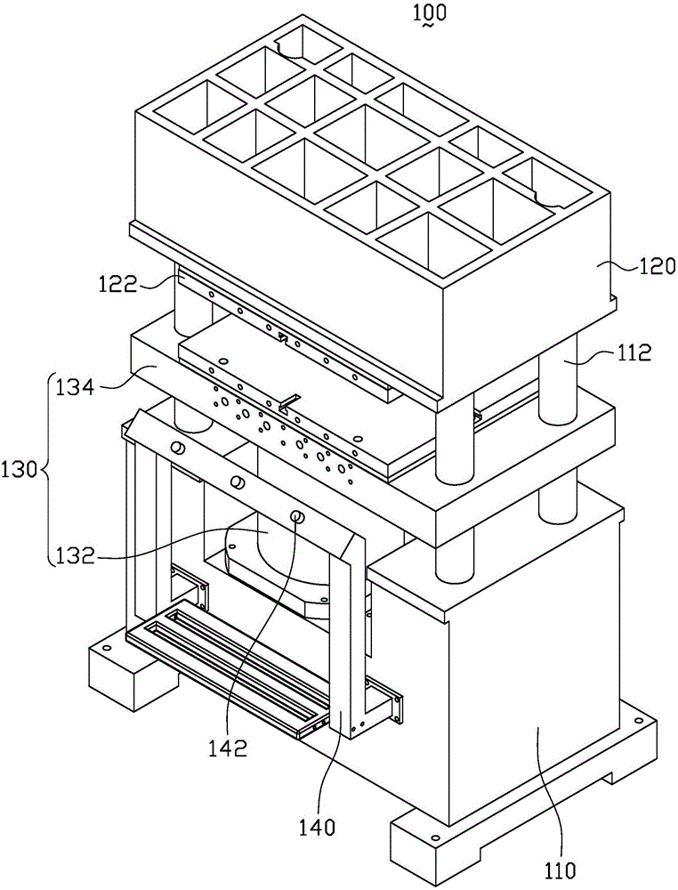
[0028] figure 1 It is a three-dimensional structure schematic diagram of the relief forming device...


PUM


Abstract

The invention discloses a relief molding process comprising the steps of making a corresponding female die according to a selected pattern; sticking a hot melting core layer to a bottom-layer fabric, and sticking a surface-layer fabric to the hot melting core layer to form a molding material strip; arranging the female die on a relief molding device; placing the molding material strip on the relief molding device, and enabling the surface-layer fabric of the molding material strip to face the female die; carrying out hot compression on the molding material strip at least twice by using the relief molding device, wherein the hot compression temperature is 50-200 DEG C, the pressure firstly exerted on every square centimeter of molding material strip is 0.1-4MPa, and the first pressure exerting time is within 1-10s; carrying out second hot compression on the molding material strip by using the relief molding device to form a relief product, wherein the pressure secondly exerted on every square centimeter of molding material strip is 0.1-2MPa, and the second pressure exerting time is within 1-10s; and cooling the relief product by using the relief molding device before die opening. By using the relief molding process, a relief with a clear pattern can be made, and the relief product is high in production efficiency and low in production cost. The invention also relates to the relief molding device and the relief product.

Description

technical field [0001] The invention relates to the technical field of relief production, in particular to a relief forming process, a relief forming device and relief products. Background technique [0002] Leather is a very flexible product, and it can be used properly to produce various leather carving crafts with beautiful patterns. Usually, the production methods of these leather carving handicrafts mainly fall into the following four categories: the first category is to use ultraviolet light holographic replication technology to make pictures on leather; Leather fixatives and brighteners are used to make genuine leather engravings; the third category is to print various patterns on leather by printing machines or surface printing processes; the last category is the process of embossing directly on the leather surface. What adopt these methods to make is all one-dimensional or two-dimensional pattern, lacks three-dimensional sense, and artistic effect is poor, let alon...

Claims


Application Information

Patent Timeline
Patent Type & Authority Applications(China)
IPC IPC(8): B44C1/24B32B37/06B32B37/08B32B37/10B32B38/06B32B9/02B32B9/04B32B15/04B32B15/082B32B27/06B32B27/08B32B27/10B32B27/12B32B27/30B32B29/00B32B5/02B32B33/00
CPCB32B5/02B32B5/18B32B5/245B32B9/025B32B9/04B32B9/046B32B15/04B32B15/046B32B27/06B32B27/065B32B27/304B32B29/002B32B29/007B32B33/00B32B37/06B32B37/08B32B37/10B32B38/06B32B2309/02B32B2309/12B44C1/24
Inventor 罗实
Owner 罗实
Why Eureka
Try Eureka