Train sleeping berth room, sleeping berth unit and bullet train hard sleeper

A technology for sleepers and trains, applied in sleeper appliances, transport buses, transport buses, etc., can solve the problems of no place to hang coats and trousers, difficult assembly, limited berths, etc., achieve beautiful and smooth curved surfaces, improve production efficiency, The effect of reducing the difficulty of assembly

Active Publication Date: 2016-07-06
广州广冷华旭制冷空调实业有限公司 +1
View PDF6 Cites 6 Cited by
  • Summary
  • Abstract
  • Description
  • Claims
  • Application Information

AI Technical Summary

Problems solved by technology

[0002] The traditional hard sleeper for high-speed trains is assembled into a sleeper room with two left and right partition walls, side walls near the windows, roof and bed boards, and the sleeper room is divided into left and right partition walls, side walls, roof boards, beds, tables and other components. Carry out on-site combination assembly on the vehicle, which is inefficient and difficult to assemble
At the same time, there is no place to hang the coats and trousers that passengers take off when going to bed in traditional hard sleeper trains. Stacking them on the bed will not only affect the sleeping space of passengers, but also cause the clothes to wrinkle.
In addition, the sleeper rooms are arranged along one side of the car length direction, and the other side is the passageway, so that the sleeper rooms of the bullet train can only be installed in one row along the car length direction, and the number of berths is limited.

Method used


Image

  • Train sleeping berth room, sleeping berth unit and bullet train hard sleeper
  • Train sleeping berth room, sleeping berth unit and bullet train hard sleeper
  • Train sleeping berth room, sleeping berth unit and bullet train hard sleeper

Examples


Embodiment Construction

[0022] In order to facilitate the understanding of the present invention, the present invention will be described more fully below with reference to the associated drawings. Preferred embodiments of the invention are shown in the accompanying drawings. However, the present invention can be embodied in many different forms and is not limited to the embodiments described herein. On the contrary, these embodiments are provided to make the understanding of the disclosure of the present invention more thorough and comprehensive.

[0023] It should be noted that when an element is referred to as being “fixed” to another element, it can be directly on the other element or there can also be an intervening element. When an element is referred to as being "connected to" another element, it can be directly connected to the other element or intervening elements may also be present. The terms "vertical," "horizontal," "left," "right," and similar expressions are used herein for purposes ...


PUM


Abstract

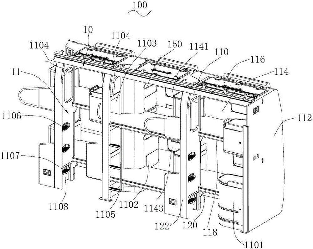
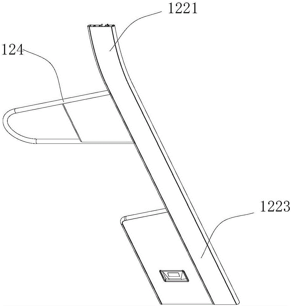
A train sleeping berth room comprises an integrally-formed sleeping berth body. The sleeping berth body comprises a first partition wall, a second partition wall, a top plate, an upper berth board, a lower berth board, a vertical wall and a guard bar, wherein the first partition wall and the second partition wall are vertically arranged, the top plate is connected to the top of the first partition wall and the top of the second partition wall, and the upper berth board and the lower berth board are parallel and located below the top plate. The vertical wall is arranged on the outer side of the first partition wall and / or the second partition wall and comprises an arc section connected with the top plate and a straight board section connected with the arc section. The guard bar and the vertical wall are integrally arranged. The sleeping berth body of the train sleeping berth room is integrally formed, assembling difficulty is lowered, and production efficiency is improved. The vertical wall in the sleeping berth body is integrally designed according to the arc of the first partition wall and the arc of the second partition wall in the train sleeping berth room, and the curved surface is attractive and smooth in modeling. Moreover, the vertical wall and the guard bar are integrally designed, and the appearance is attractive and elegant. The invention further relates to a sleeping berth unit and a bullet train hard sleeper.

Description

technical field [0001] The invention relates to the technical field of train interior decoration structures, in particular to a train sleeper room, a sleeper unit and a train hard sleeper. Background technique [0002] The traditional hard sleeper for high-speed trains is assembled into a sleeper room with two left and right partition walls, side walls near the windows, roof and bed boards, and the sleeper room is divided into left and right partition walls, side walls, roof boards, beds, tables and other components. On-site combination assembly on the vehicle is inefficient and difficult to assemble. At the same time, there is no place to hang the coats and trousers that passengers take off when going to bed in traditional hard sleepers. Stacking them on the beds will not only affect the sleeping space of passengers, but also cause the clothes to wrinkle. In addition, the sleeper rooms are arranged along one side of the car length direction, and the other side is the passa...

Claims


Application Information

Patent Timeline
Patent Type & Authority Applications(China)
IPC IPC(8): B61D1/08B61D31/00
CPCB61D1/08B61D31/00
Inventor 罗章陶范锐标杨余张哲
Owner 广州广冷华旭制冷空调实业有限公司
Why Eureka
Try Eureka