
Pipe gallery installation infrastructure, comprehensive pipe gallery and installation and construction methods

A technology for installing foundation and comprehensive pipe gallery, which is applied in basic structure engineering, underwater structures, artificial islands, etc., can solve the problems of poor settlement capacity, uneven resistance, long construction period, etc., and achieves low production cost, installation and construction operation. Simple and convenient construction

Active Publication Date: 2019-01-18
SHENZHEN HUAHAN URBAN COMPREHENSIVE PIPE GALLERY TECH RES DEV CO LTD
View PDF5 Cites 0 Cited by
  • Summary
  • Abstract
  • Description
  • Claims
  • Application Information

AI Technical Summary

Problems solved by technology

[0005] The third technical problem to be solved by the present invention is to provide a comprehensive pipe gallery installation and construction method, which overcomes the defects of the existing technology such as long construction period, many consumables, high cost, and poor anti-uniform settlement ability.

Method used


Image

  • Pipe gallery installation infrastructure, comprehensive pipe gallery and installation and construction methods
  • Pipe gallery installation infrastructure, comprehensive pipe gallery and installation and construction methods
  • Pipe gallery installation infrastructure, comprehensive pipe gallery and installation and construction methods

Examples


Embodiment Construction

[0074] The present invention will be further described below in conjunction with the drawings and embodiments.

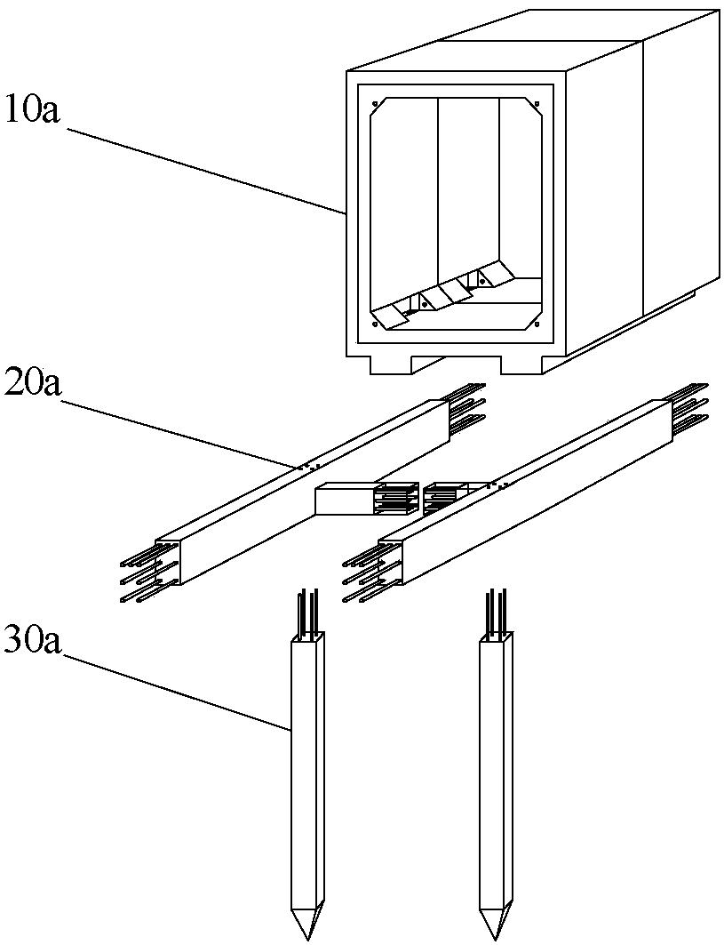
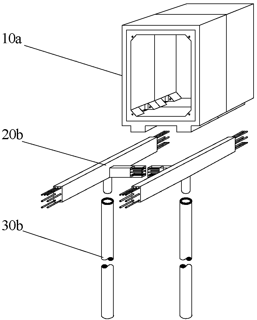
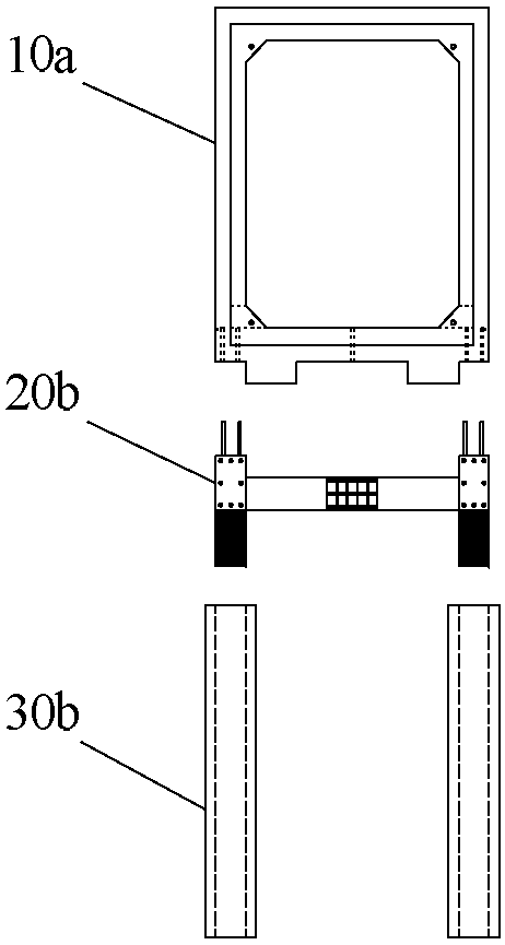
[0075] Such as Figure 1 to Figure 4 As shown, the pipe gallery installation base structure of the present invention includes frame beams 20a, 20b and precast piles 30a, 30b.

[0076] The sash beams 20a and 20b include main beams arranged in parallel and spaced apart and cross beams connecting adjacent main beams.

[0077] The precast piles 30a, 30b are vertically spaced at the bottom of the main beams of the frame beams 20a, 20b, and the center lines of the precast piles 30a, 30b are adapted to the vertical center plane of the main beam. The fit means that the centerline of the precast piles 30a, 30b can be located in the vertical center plane of the main beam, or near the vertical center plane of the main beam, to ensure that the pressure transmitted by the main beam to the precast piles 30a, 30b is located The center of the prefabricated piles 30a, 30b is located near ...


PUM


Abstract

The invention provides a pipe rack installation base structure, a comprehensive pipe rack and an installation and construction method of the comprehensive pipe rack. The base structure comprises sash beams and prefabricated piles. The sash beams comprise main beams and cross beams. The main beams are matched with the bottoms of pipe rack prefabricated parts to achieve transverse positioning. The prefabricated piles are arranged at the bottoms of the main beams of the sash beams at intervals, and the center lines of the prefabricated piles are matched with the vertical central planes of the main beams. The tops of the prefabricated piles and the bottoms of the main beams are connected through connecting structures A. Each main beam comprises a connecting structure B connected with the corresponding pipe rack prefabricated part. The connecting structures B are arranged on the main beams at intervals corresponding to the pipe rack prefabricated parts. The pipe rack comprises the pipe rack prefabricated parts, sealing devices and the pipe rack installation base structure. The method comprises the steps of pile driving, foundation pit excavation, chopping of pile heads, installation of the sash beams, backfilling of a gravel sand bed, grouting and filling, waterproof construction and foundation pit backfilling. The pipe rack installation base structure, the comprehensive pipe rack and the installation and construction method of the comprehensive pipe rack have the advantages that the production cost is low, transportation is convenient, the construction speed is high, the integrity, rigidity and earthquake resistance of the pipe rack are good, and the structure is resistant to floating and uneven foundation settlement and has high practical value on soft soil areas.

Description

Technical field [0001] The invention relates to an installation base structure for an underground comprehensive pipe gallery, and also relates to an underground comprehensive pipe gallery adopting the installation base structure and an installation and construction method of the comprehensive pipe gallery. Background technique [0002] The prefabricated integrated pipe gallery has many advantages such as high efficiency, energy saving, environmental protection, cost reduction, and improvement of the function and performance of the pipe gallery, and it has a wide range of application prospects. Because the prefabricated integrated pipe gallery has the defects of poor integrity, rigidity, anti-floating and seismic performance, its application in silt areas such as coastal cities is restricted. The traditional solution is: first treat the soft foundation, such as setting up cement mixing piles, high-pressure jet grouting piles, etc., to harden the silt soft soil, then excavate the f...

Claims


Application Information

Patent Timeline
Patent Type & Authority Patents(China)
IPC IPC(8): E02D29/045E02D27/12
CPCE02D27/14E02D29/045
Inventor 郑能欢杨春江巫可可张行霖
Owner SHENZHEN HUAHAN URBAN COMPREHENSIVE PIPE GALLERY TECH RES DEV CO LTD
Learn More