Real-time monitoring and alarming system of intelligent well lid

A real-time monitoring and alarm system technology, applied in water conservancy projects, artificial islands, underwater structures, etc., can solve the problems of different alarm modules and warning modules, high installation and production costs, and susceptibility to radiation shielding, etc., to achieve obvious warnings , reduce the overall cost, and ensure the effect of warning

Inactive Publication Date: 2016-07-06
BEIJING ZKTOP INFORMATION TECH CO LTD
View PDF7 Cites 5 Cited by
  • Summary
  • Abstract
  • Description
  • Claims
  • Application Information

AI Technical Summary

Problems solved by technology

[0004] But it still has some problems, such as the open patent: CN105297781A: 1. Its antenna is located in the cellar well, which is easily shielded by radiation, making the radiation ability weak, resulting in a decrease in communication distance and an increase in system cost; 2. Its alarm module and warning module Instead of adopting an integrated structure, the on-site installation is troublesome, and the installation and production costs are high

Method used


Image

  • Real-time monitoring and alarming system of intelligent well lid
  • Real-time monitoring and alarming system of intelligent well lid
  • Real-time monitoring and alarming system of intelligent well lid

Examples


Embodiment 1

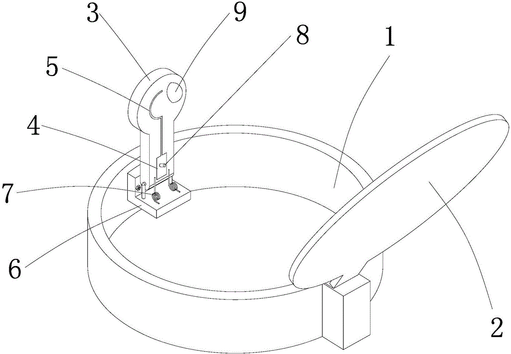
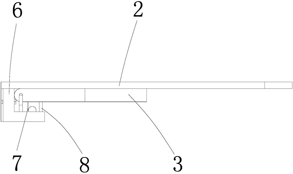
[0026] Such as Figures 1 to 3 As shown, a real-time monitoring and alarm system for an intelligent manhole cover includes a warning sign 3, a monitoring module 4, a base 6 and an antenna 5. The base 6 is fixed on the well wall 1 by screws, and the warning sign 3 is hinged on the base 6. Of course, in In other embodiments, the warning sign 3 can also be directly hinged on the well wall 1, and a spring 7 is arranged between the warning sign 3 and the base 6. In this embodiment, it is a torsion spring. Of course, in other embodiments, it is also It can be other elastic parts such as shrapnel. One end of the torsion spring 7 is fixed on the warning sign 3, and the other end is fixed on the base 6. When the well cover 3 is buckled on the pit well, the warning sign 3 is against the lower surface of the well cover 2, and the torsion spring 7 is under stress. When the well cover is removed , the warning sign 3 turns upwards under the action of the torsion spring 7, and stretches out...

Embodiment 2

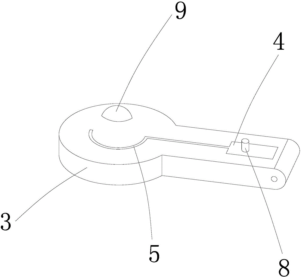
[0030] The difference between this embodiment and Embodiment 1 is that: Figure 4 As shown, the warning sign 3 is sleeved in the base 6, the base 6 is provided with a sleeve 61, the warning sign 3 is arranged in the sleeve 61, and an elastic member 7 is arranged between the warning sign 3 and the sleeve 61. In the embodiment, it is a compression spring, of course, in other embodiments, it may also be other elastic members such as shrapnel. One end of the spring 7 is fixed on the bottom of the warning sign 3, and the other end is fixed on the base 6. When the well cover 3 is buckled on the pit well, the warning sign 3 is against the lower surface of the well cover 2, and the spring 7 is in a compressed state. When the well cover is removed , the warning sign 3 bounces upwards under the elastic force of the spring 7, stretches out of the cellar well and warns, to remind pedestrians and vehicles to pay attention to avoid accidents, of course, Figure 4 Just provided a kind of em...


PUM


Abstract

The invention relates to the field of municipal facilities, in particular to an intelligent manhole cover real-time monitoring and alarm system. The invention discloses an intelligent manhole cover real-time monitoring and alarm system, which includes a warning sign, a monitoring module and an antenna. Above, the signal output terminal of the monitoring module is connected to the antenna, and the connection between the warning sign and the well wall is provided with an elastic member. Through the driving force of the elastic member, when the well cover is removed, the warning sign will Under the action of force, it extends out of the cellar well to warn, and at the same time, the monitoring module sends out alarm information and transmits it to the monitoring center through the antenna for alarm. The invention has long communication distance, convenient installation, low cost, long service life and good use effect.

Description

technical field [0001] The invention belongs to the field of municipal facilities, in particular to an intelligent well cover real-time monitoring and alarm system. Background technique [0002] With the further acceleration of the urbanization process, the construction of municipal public facilities has developed rapidly. Municipal, electric power, communication, gardening and other departments have a large number of municipal objects, equipment, assets, etc. that need to be managed, such as cables, equipment boxes, manhole covers, street light poles, trash cans, ancient wood, etc. Due to the lack of effective real-time monitoring and management methods, a large number of outdoor assets of municipal public facilities, such as manhole covers, are missing, displaced or damaged due to human theft, external force impact or flood impact, posing safety hazards and seriously affecting vehicles on the road , Pedestrian travel safety, causing huge direct or indirect economic losses...

Claims


Application Information

Patent Timeline
Patent Type & Authority Applications(China)
IPC IPC(8): E02D29/14
CPCE02D29/1481
Inventor 洪毅洪浩
Owner BEIJING ZKTOP INFORMATION TECH CO LTD
Why Eureka
Try Eureka