
Shrinkage heap leaching subsequent filling mining method used for steeply-inclined thin orebody

A technology of filling mining and mining methods, which is applied to filling materials, mining equipment, earth cube drilling and mining, etc., which can solve the problems of surface deformation and damage, low mining cost, poor effect of rich liquid, etc., and achieve less loss and dissipation and low mining cost , the effect of reducing workload

Active Publication Date: 2016-07-06
武汉科技大学资产经营有限公司
View PDF7 Cites 14 Cited by
  • Summary
  • Abstract
  • Description
  • Claims
  • Application Information

AI Technical Summary

Problems solved by technology

The mining cost of the solution mining method is relatively low, and some scholars put forward the idea of ​​combining the solution mining method and the ore retention mining method to mine underground ore bodies (Xie Jianbing, Zhu Heling, Zhang Xinguang. Research on the heap leaching method of the ore retention in mines and application [J]. Nonferrous Metals (Mine Section), 2009, 61(2): 4-6.), but due to the disordered seepage of the leaching solution, the rich solution after leaching is collected by the stope shaft At the same time, when the open heap leaching method is adopted, the method uses the forced collapse of the top pillar to deal with the remaining empty area of ​​the stope. Since the structure of the ore pile in the stope is relatively loose, the settlement of the ore pile after the top pillar collapses May cause deformation and destruction of the surface

Method used


Image

  • Shrinkage heap leaching subsequent filling mining method used for steeply-inclined thin orebody
  • Shrinkage heap leaching subsequent filling mining method used for steeply-inclined thin orebody
  • Shrinkage heap leaching subsequent filling mining method used for steeply-inclined thin orebody

Examples


Embodiment 1

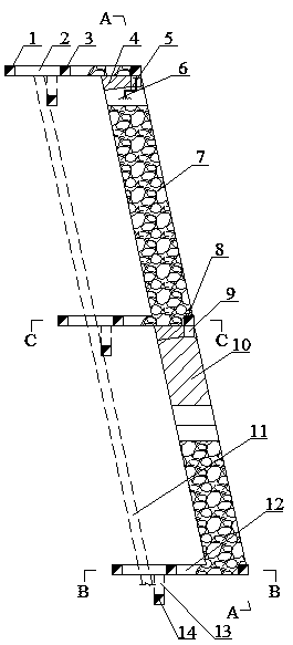
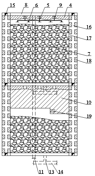
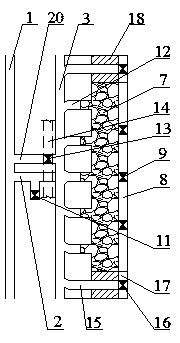
[0037] A mining method for heap leaching with retained ore followed by filling for steeply inclined thin ore bodies. The steeply inclined thin ore body described in this example is an underground copper silicate deposit in my country. The strike length of the ore body is 100-140m, the dip angle is 70-75°, the average thickness is 4m, and the buried distance is 250m from the surface. The footwall of the ore body is quartzite, the hanging wall is diorite, the ore body and surrounding rock are relatively stable, and the ore rock's Platts coefficient is f=6~10.

[0038] The concrete steps of mining method described in the present embodiment are as follows:

[0039] 1) Accurate cutting

[0040] After the completion of the development project, such as Figure 1~Figure 4 As shown, the vein-piercing roadway (2) is excavated from the stage transportation roadway (1) to the room to be mined, and the tunnel-piercing roadway (2) is excavated along the ore body toward the mine-exiting ro...


PUM


Abstract

The invention relates to a shrinkage heap leaching subsequent filling mining method used for a steeply-inclined thin orebody. According to the technical scheme, after accurate mining is completed, undercutting is conducted on the bottom of a chamber, and after filling shafts (9) are tunneled, artificial anti-seepage concrete false bottoms are laid on the bottom of the undercut space; artificial anti-seepage false lanes (8) are constructed, and the orebody (10) to be mined in the chamber is recovered from bottom to top in a layered mode; after each time of ore breaking by blasting, minerals covering 20%-30% of the volume of the ore broken by blasting of each time are discharged and are conveyed to the earth ground through an underground lifting and conveying system, and a heap is formed on the earth ground for leaching; after recovery and heap formation are completed, sprayers (6) arranged in the chamber spray a leaching solution to the ore heap (7), the infiltrated leaching solution is gathered to a liquid collection driftway (14) through an ore discharging lane (12) and an ore discharging lane linking way (3); and after heap leaching mining is completed, stope mined-out zones are filled with barren rocks (23), and then roof-contact filling is conducted on a stope. The method has the characteristics of being high in liquid collection efficiency, good in stope roof-contact effect and low in mining cost.

Description

technical field [0001] The invention belongs to the field of mining methods for steeply inclined thin ore bodies. In particular, it relates to a mining method for heap leaching with ore retention followed by filling for steeply inclined thin ore bodies. technical background [0002] For the mining of underground steeply inclined thin ore bodies, the traditionally commonly used mining methods are empty field method or filling method. Open-pit mining will leave more gobs underground, forming potential safety hazards and threatening the safety of surface facilities and personnel in the mining area. It does not meet the country's strategic requirements for building a resource-saving and environment-friendly society, and will gradually be eliminated. disuse. At this stage, more and more attention is paid to the filling method, and it is also a mining method advocated by the state. However, the filling method needs to fill the goaf, and the mining cost is relatively high. With...

Claims


Application Information

Patent Timeline
IPC IPC(8): E21D9/10E21F15/00
CPCE21D9/10E21F15/00
Inventor 刘艳章陈小强潘世华张群张丙涛邹晓甜叶义成柯丽华王文杰张奎吴恩桥刘永涛
Owner 武汉科技大学资产经营有限公司
Features
  • Generate Ideas
  • Intellectual Property
  • Life Sciences
  • Materials
  • Tech Scout
  • Unparalleled Data Quality
  • Higher Quality Content
  • 60% Fewer Hallucinations
Learn More