Supercharge Your Innovation With Domain-Expert AI Agents!

Grease distribution rack and construction elevator grease lubricating complete equipment

A technology for the construction of elevators and complete sets of equipment, applied in the directions of mechanical equipment, lubricating parts, engine lubrication, etc., can solve the problems of inability to achieve lubrication effect, dangerous high-altitude operation, poor spray orientation, etc., and achieves excellent practicability and economy. , the effect of wide application and low manufacturing cost

Active Publication Date: 2016-07-06
张巍
View PDF10 Cites 0 Cited by
  • Summary
  • Abstract
  • Description
  • Claims
  • Application Information

AI Technical Summary

Problems solved by technology

[0004] Due to the lack of suitable grease distributors, many dry oil centralized lubrication equipment that has been produced on a large scale have become useless, so that the entire construction industry in China still generally adopts the backward manual lubrication method of regular grease lubrication for construction elevators, which is dirty. Tired, time-consuming and fuel-intensive, and dangerous high-altitude operations
[0005] Most of the existing lubrication methods for construction elevators use oil injection (mist), which can only use thin oil, poor spray orientation, and solidification in a short time, which cannot achieve the ideal lubrication effect. In the end, the method of artificial buttering was adopted.

Method used


Image

  • Grease distribution rack and construction elevator grease lubricating complete equipment
  • Grease distribution rack and construction elevator grease lubricating complete equipment
  • Grease distribution rack and construction elevator grease lubricating complete equipment

Examples


Embodiment Construction

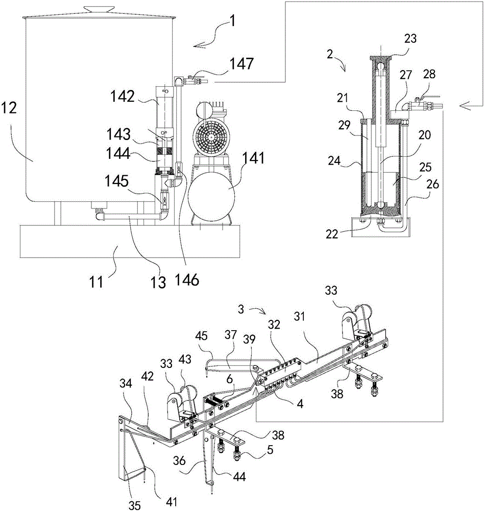
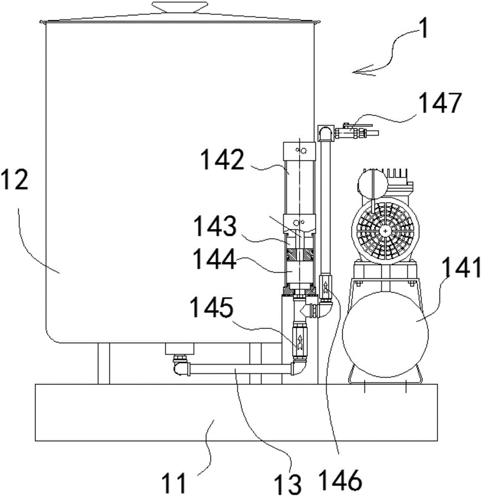
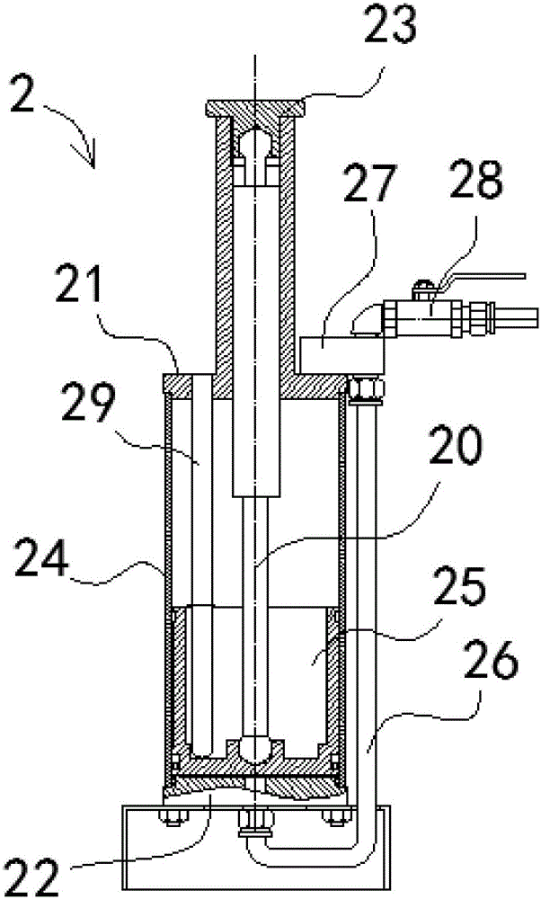
[0030] Embodiments of the present invention are described in detail below, examples of which are shown in the drawings, wherein the same or similar reference numerals represent the same or similar elements or elements having the same or similar functions throughout.

[0031] In the description of the present invention, it should be noted that for orientation words, such as the term "center", "horizontal", "longitudinal", "length", "width", "thickness", "upper", "lower" , "Front", "Back", "Left", "Right", "Vertical", "Horizontal", "Top", "Bottom", "Inner", "Outer", "Clockwise", "Counterclockwise " and other indication orientations and positional relationships are based on the orientations or positional relationships shown in the drawings, and are only for the convenience of describing the present invention and simplifying the description, rather than indicating or implying that the device or element referred to must have a specific orientation, or in a specific orientation. The...


PUM


Abstract

The invention discloses a grease distribution rack and construction elevator grease lubricating complete equipment. The grease distribution rack comprises grease applying wheels, side wheel bent feet, positive pressure wheel bent feet, a climbing gear bent foot, a rack back gear bent foot, installing feet, a vertical plate and an adjustable distribution block. The adjustable distribution block is arranged on the vertical plate and provided with an oil inlet and outlet connector and a plurality of oil outlet pipes. The grease applying wheels are arranged on one or two sides of the vertical plate. The side wheel bent feet are arranged on the two sides of the vertical plate. The positive pressure wheel bent feet are connected to the side wheel bent feet. The grease distribution rack has the beneficial effects of being simple and practical in structure, low in manufacturing cost, stable in running and wide in application range, meanwhile, using and operating are convenient and fast, and functions of a dynamic energy supplying host, energy accumulating usage and distributed conveying are integrated. Automatic grease lubrication is conducted on a construction elevator so as to thoroughly change the lagging situations that in original construction elevator manual grease applying, complexity and overwork exist, time and grease are consumed, and danger exists due to standing at the high position. Thus, the grease distribution rack and the construction elevator grease lubricating complete equipment are products excellent in technicality, practicability and economical efficiency.

Description

【Technical field】 [0001] The invention relates to a grease-lubricated executive mechanism--grease diverter frame; it is specially used for construction elevators that require periodic centralized lubrication, and can separately grease-lubricate the gear rack and each roller; [0002] The invention also relates to a complete set of construction elevator grease lubrication equipment. 【Background technique】 [0003] Construction elevators are the main equipment for vertically transporting building materials in building construction. They must be used in high-rise building construction. During use, the guide rail rollers and gear racks must be lubricated with grease. At present, the construction elevator products produced by domestic manufacturers use artificial Grease regularly, [0004] Due to the lack of suitable grease distributors, many dry oil centralized lubrication equipment that has been produced on a large scale have become useless, so that the entire construction ind...

Claims


Application Information

Patent Timeline
IPC IPC(8): F16N25/00F16N7/38
CPCF16N7/385F16N25/00F16N2210/24
Inventor 张巍
Owner 张巍
Features
  • R&D
  • Intellectual Property
  • Life Sciences
  • Materials
  • Tech Scout
  • Unparalleled Data Quality
  • Higher Quality Content
  • 60% Fewer Hallucinations
Learn More