
Natural gas liquefaction system and method based on plate heat exchanger and modular mixed refrigerant

A technology of mixed refrigerant and plate heat exchanger, which is applied in the direction of refrigeration and liquefaction, liquefaction, cold treatment separation, etc., can solve the problems of unfavorable equipment modularization, complicated process, and inappropriateness, so as to facilitate equipment modularization and simplify purification equipment , adaptable effect

Inactive Publication Date: 2016-07-06
SHANGHAI JIAO TONG UNIV
View PDF8 Cites 4 Cited by
  • Summary
  • Abstract
  • Description
  • Claims
  • Application Information

AI Technical Summary

Problems solved by technology

However, for small skid-mounted natural gas liquefaction plants, the mixed refrigerant liquefaction process is relatively complicated
[0006] After searching, the patent publication number CN102477327A, the patent titled "a small and medium-sized natural gas liquefaction process", discloses a small and medium-sized natural gas liquefaction process. In this process, the mixed refrigerant adopts two-stage gas-liquid separation, and there are three heat exchange device, the process is more complicated, not suitable for modular natural gas liquefaction plant
[0007] Patent Publication No. CN102445052A, titled "A Biogas Liquefaction Process and Device for Scattered Source Points", uses a double-mixed refrigeration cycle to liquefy biogas from scattered gas sources. Since the process consists of two separate refrigeration cycles , there are many equipments and the process is complicated, which is not conducive to the modularization of equipment. At the same time, the components of biogas and natural gas are quite different, so they cannot be applied to modular natural gas liquefaction plants.
[0008] The existing natural gas liquefaction process has very high requirements for natural gas purification equipment, because the conventional liquefaction cold box uses a plate-fin heat exchanger, and the flow channel of the plate-fin heat exchanger is very small. If the natural gas purification equipment cannot remove carbon dioxide to a very high level Low content, solid carbon dioxide is very easy to block the flow channel of the plate-fin heat exchanger at low temperature

Method used


Image

  • Natural gas liquefaction system and method based on plate heat exchanger and modular mixed refrigerant

Examples


Embodiment

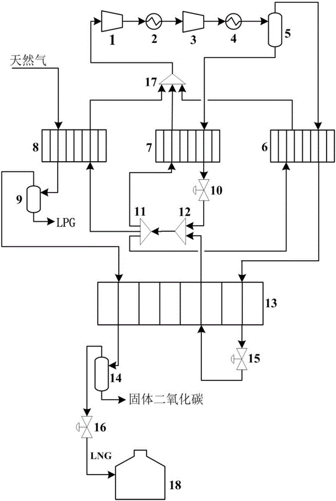
[0059] Natural gas molar composition 93% CH 4 +4%C 3 h 8 +2%N 2 +1%CO 2 , pressure 4.0MPa, temperature 40°C, flow rate 1kmol / h; mixed refrigerant flow rate 2.68kmol / h. The specific steps of the modular mixed refrigerant natural gas liquefaction process based on plate heat exchangers are as follows:

[0060] 1. The natural gas raw material is cooled to -40°C by the natural gas pre-cooling heat exchanger;

[0061] 2. The natural gas after step cooling enters the heavy hydrocarbon separator 9, and obtains heavy hydrocarbons from the bottom 2;

[0062] 3. The natural gas cryogenic heat exchanger 13 after removing heavy hydrocarbons in step 2 is cooled to -15°C;

[0063] 4. The natural gas obtained in step 3 enters the carbon dioxide separator 14, the liquefied natural gas flows out from the top of the carbon dioxide separator 14, and the solid carbon dioxide is separated from the bottom of the carbon dioxide separator 14;

[0064] 5. The liquefied natural gas after removing...


PUM


Abstract

The invention provides a natural gas liquefaction system and method based on a plate heat exchanger and a modular mixed refrigerant. The system comprises a plate heat exchanger liquefaction cold box module, a carbon dioxide purification module, a mixed refrigerant compression module and a natural gas storage module; the plate heat exchanger liquefaction cold box module is successively connected with the carbon dioxide purification module and the natural gas storage module to form a natural gas liquefaction loop; the mixed refrigerant compression module is connected with the plate heat exchanger liquefaction cold box module to form a refrigerant refrigeration circulation loop; the natural gas liquefaction loop is used for dehydrating, cooling, removing heavy hydrocarbon, cooling and liquefying, and reducing the pressure of natural gas as a raw materials, and then storing the natural gas; and the refrigerant refrigeration circulation loop is used for circularly using the mixed refrigerant to cool the natural gas. A liquefaction technology is simple in technological process, the number of equipment is small, energy consumption is low, and the natural gas liquefaction system is integrated with a carbon dioxide desorption module, and meanwhile has relatively high adaptability to different gas sources.

Description

technical field [0001] The invention relates to the technical field of chemical engineering and cryogenic engineering, in particular to a modular mixed refrigerant natural gas liquefaction system and method based on plate heat exchangers. Background technique [0002] As the main fossil energy in the world, natural gas, oil and coal account for a large proportion of primary energy. As a high-quality clean energy, natural gas has been valued by more and more countries. [0003] With the continuous optimization of my country's energy structure and the continuous growth of natural gas consumption demand, coupled with the current situation that most of my country's natural gas fields are not large, the gap between my country's natural gas supply and demand is constantly increasing. It is predicted that by 2020 my country's natural gas supply gap will reach 1000×10 8 m 3 . [0004] On the other hand, there are a large number of marginal gas fields, associated gas fields, and ...

Claims


Application Information

Patent Timeline
IPC IPC(8): F25J1/02F25J5/00
CPCF25J1/0022F25J1/0055F25J1/0212F25J1/0265F25J2205/20F25J2220/64F25J2220/66F25J1/0237F25J5/00
Inventor 巨永林贺天彪
Owner SHANGHAI JIAO TONG UNIV
Learn More