Projection system

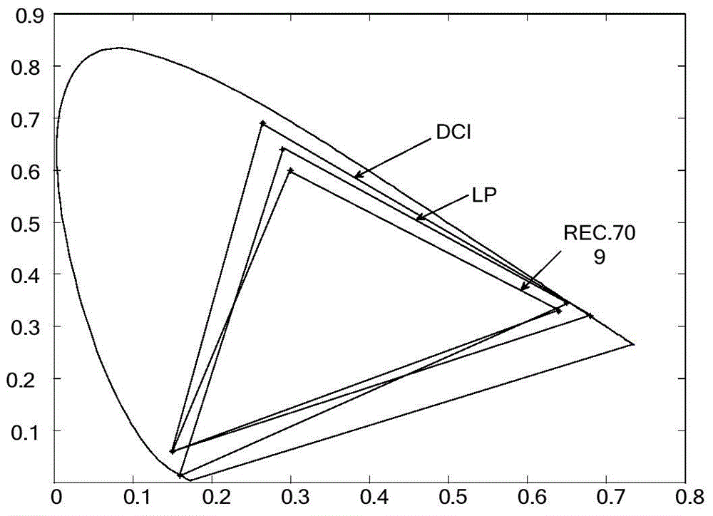
A technology of a projection system and a light source system, applied in the field of projection systems, can solve the problems of small color gamut of color images, unable to meet the REC.709 standard and DCI standard, etc., and achieve the effects of low cost, simple structure and wide color gamut

Active Publication Date: 2016-07-06
APPOTRONICS CORP LTD
View PDF6 Cites 17 Cited by
  • Summary
  • Abstract
  • Description
  • Claims
  • Application Information

AI Technical Summary

Problems solved by technology

[0006] In view of this, the present invention provides a projection system to solve the problem that the color gamut of the color image synthesized by the DLP projection system in the prior art is small and cannot meet the REC.709 standard and the DCI standard

Method used


Image

  • Projection system
  • Projection system
  • Projection system

Examples


Embodiment 1

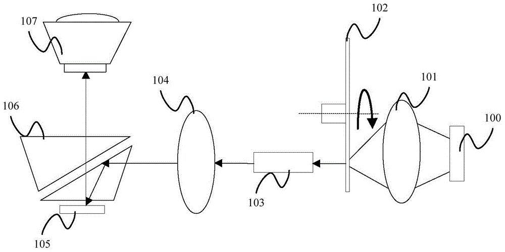
[0066] This embodiment provides a projection system, including a light source system, a light splitting device, a first light modulation device and a second light modulation device. Wherein, the light source system generates the first light beam at the first time sequence, and generates the second light beam at the second time sequence; the light splitting device sequentially divides the first light beam and the second light beam into the light transmitted along the first optical path and the light transmitted along the second optical path ; The first light modulation device modulates the light transmitted along the first optical path, and the second light modulation device modulates the light transmitted along the second optical path.

[0067] The first light modulation device and the second light modulation device in this embodiment include but are not limited to DMD (DigitalMicromirrorDevice, digital micromirror device), LCOS (LiquidCrystalOnSilicon, liquid crystal display o...

Embodiment 2

[0088] This embodiment provides a projection system. The structure of the projection system provided by this embodiment is substantially the same as that of the projection system provided by Embodiment 1, and both include a light source system, a spectroscopic device, a first light modulation device and a second light modulation device, And, the light source system in this embodiment also includes the first light source 401 that emits the first light λ1 and the second light source 402 that emits the first compensation light λ2, and the first light source 401 is a laser light source that emits blue light, and the second light source 402 It is a laser light source that emits blue light. Similarly, the first compensation light in this embodiment is blue light with a narrow spectrum.

[0089] The difference between the projection system provided in this embodiment and the projection system provided in Embodiment 1 is that the light source system in this embodiment includes the firs...

Embodiment 3

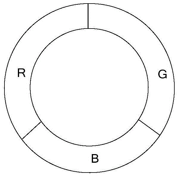
[0100] This embodiment provides a projection system. The structure of the projection system provided by this embodiment is substantially the same as that of the projection system provided by Embodiment 1, and both include a light source system, a spectroscopic device, a first light modulation device and a second light modulation device, The difference is that, if Figure 16 As shown, the light source system in this embodiment includes a first light source 401 and a first rotating color wheel 1600 .

[0101] The first light source 401 is used to emit the first light λ1, preferably, the first light source 401 is a laser emitting blue light. The first rotating color wheel 1600 includes a first fluorescent color segment and a second fluorescent color segment, the first fluorescent color segment and the second fluorescent color segment are rotated to the optical path of the first light λ1 in turn, and the first fluorescent color segment is used to absorb the first fluorescent color...


PUM


Abstract

The invention provides a projection system, comprising a light source system generating a first light beam in a first sequence, and generating a second light beam in a second sequence, wherein the first light beam comprises first light and first compensation light, and the second light beam comprises second light, or the second light beam comprises the second light and first compensation light; a beam split device sequentially dividing the first light beam and the second light beam into the light transmitted along a first optical path, and the light transmitted along a second optical path; a first light modulation device modulating the light transmitted along the first optical path; and a second light modulation device modulating the light transmitted along the second optical path light. The projection system employs the first compensation light to compensate for the first light or the second light, and allows a wider color gamut of a combined color image, thereby satisfying REC. 709 and DCI color gamut standards more; in addition, the projection system employs two light modulation devices to modulate images, and has the characteristics of higher luminous efficiency and brightness, simpler structure and lower cost.

Description

technical field [0001] The present invention relates to the field of optical technology, more specifically, to a projection system. Background technique [0002] At present, DLP (Digital Light Procession, digital light processing) projection technology based on DMD (Digital Micromirror Device, digital micromirror device) has been more and more widely used. Among them, the most commonly used DLP projection systems are single-chip DMD projection systems and three-chip DMD projection systems. [0003] Monolithic DMD projection systems such as figure 1 As shown, it includes a light source 100, a collecting lens 101, a rotating color wheel 102, a square rod 103, an optical relay system 104, a DMD chip 105, a TIR prism 106 and a projection lens 107, wherein the light source 100 is a semiconductor laser or a light emitting diode. The excitation light emitted by the light source 100 is focused on the rotating color wheel 102 after passing through the collecting lens 101. Since the...

Claims


Application Information

Patent Timeline
Patent Type & Authority Applications(China)
IPC IPC(8): G03B21/20G03B21/00
CPCG03B21/005G03B21/2013G03B21/204G03B21/2053G03B33/08G03B33/12G03B33/14H04N9/3105H04N9/3111H04N9/3114H04N9/3158H04N9/3161H04N9/3164H04N9/3182H04N9/3102H04N9/3155
Inventor 郭祖强王则钦
Owner APPOTRONICS CORP LTD
Why Eureka
Try Eureka