Method for panoramic inspection on substation

A substation and panoramic technology, applied in the field of electric power system, can solve the problems of inconvenient control of motion range, low efficiency, complex environment, etc., and achieve the effect of reducing inspection omissions and improving work efficiency.

Inactive Publication Date: 2016-07-06
JIANGSU ELECTRIC POWER RES INST +3
View PDF7 Cites 14 Cited by
  • Summary
  • Abstract
  • Description
  • Claims
  • Application Information

AI Technical Summary

Problems solved by technology

[0006] (1) Inspection personnel need to inspect the entire substation. The substation has a wide area, and manual comprehensive inspection is time-consuming and laborious, and the efficiency is low;
[0007] (2) The appearance of the electrical equipment in the substation is similar, and the environment is complex. When the inspectors inspect, it is easy to confuse or lose the inspection target;
[0008] (3) The inspection personnel generally operate the instrument manually, and the range of motion is inconvenient to control, and there may be blind spots in the inspection;
[0009] (4) At present, the inspection equipment on the market is limited by technology and the field of view is limited, so it is impossible to conduct comprehensive and systematic observation of substations

Method used


Image

  • Method for panoramic inspection on substation
  • Method for panoramic inspection on substation
  • Method for panoramic inspection on substation

Examples


Embodiment 1

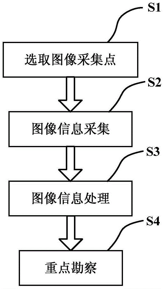
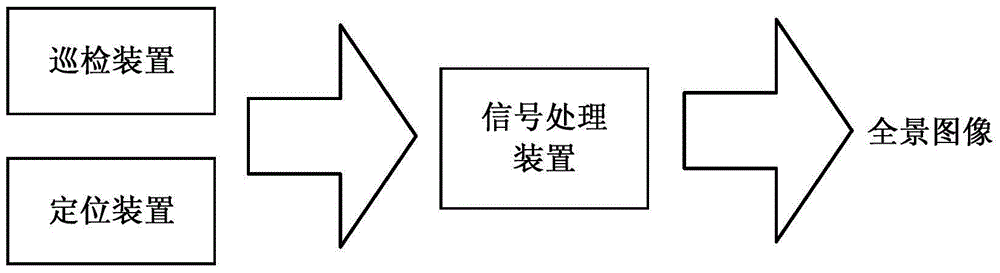
[0079] The inspection equipment uses a thermal infrared imager as the inspection device, GPS and gyroscope as the positioning device, and the positioning device and the lens of the thermal infrared imager are located on the same optical axis, so that the moving direction of the lens is consistent with the direction of the detected azimuth change. GPS and gyroscope are used to measure the coordinates of the shooting location and the orientation of the optical axis of the thermal infrared imager. When the inspector first takes a view at the center of the substation, the GPS records the geographical information at this time, and the gyroscope records the angle information.

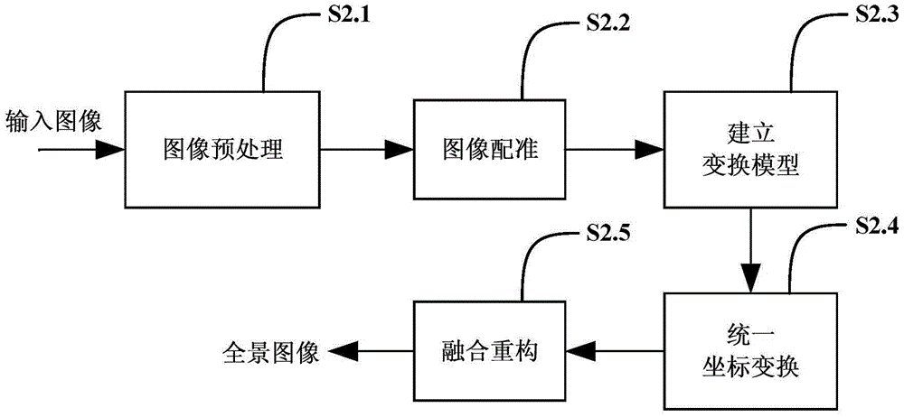
[0080] The thermal infrared imager adopts panoramic image shooting algorithm, signal processing algorithm and positioning algorithm, among which:

[0081] The panoramic image shooting algorithm can be implemented by extracting image edge features, first find out the overlapping parts of two adjacent images, an...

Embodiment 2

[0090] This solution can be applied to ultraviolet / infrared / visible three-channel portable inspection equipment. The inspection personnel carry out inspections in the substation with this system, which can detect the situation of the substation in all directions and all-weather, and match the fault points to the substation according to the image feature matching method. In the 3D model of the substation, guide the inspection personnel to go to the survey.

[0091] Ultraviolet detection technology is used for early fault detection of substation electrical equipment. Ultraviolet detection technology has the characteristics of no background and strong anti-interference ability, and has been widely used in substation inspection work; infrared detection technology is used for middle and late fault detection of substation electrical equipment ; Visible light equipment can directly observe the pollution of electrical equipment; combining the three, adding panoramic shooting algorithms...


PUM


Abstract

The invention discloses a method for panoramic inspection on a substation. The method comprises the following steps: selecting image acquisition points according to specific conditions of the substation; acquiring image information by an inspector holding inspection equipment; performing fault judgement on a panoramic image by the inspection equipment according to preset fault criteria during the process of inspection performed by the inspector holding the inspection equipment; and finally, performing key survey and maintenance aiming at a fault point. The inspection equipment comprises an inspection device, a location device and a signal processor. The method can be used for acquiring panoramic information of the substation once via image splicing technology, finding the fault point in the substation quickly and accurately, reducing omission in inspection, and improving the work efficiency of the inspector to a great extent.

Description

technical field [0001] The invention relates to the field of power systems, in particular to a panoramic inspection method for substations. Background technique [0002] The safety of the substation power grid is related to various industries such as energy and industry, and affects all nerves of the society. It is very important to ensure the safe operation of substations. The daily inspection of substations can detect electrical equipment failures in time, prevent problems before they happen, and ensure that the equipment in the substation is maintained in a timely manner. [0003] At present, the inspection work is mainly based on manual inspection. The construction area of ​​the substation is relatively large. At present, the construction area of ​​the smallest 220kv substation is 7519 square meters. The inspection lines in the station are criss-crossed, and the electrical equipment is similar. The amount is large and time-consuming, and it is easy to lose or confuse fa...

Claims


Application Information

Patent Timeline
Patent Type & Authority Applications(China)
IPC IPC(8): G07C3/00H04N5/232
CPCG07C3/00H04N23/698
Inventor 徐长福薄斌周志成陶风波胡成博陶加贵李想
Owner JIANGSU ELECTRIC POWER RES INST
Why Eureka
Try Eureka