Operating mechanism of electrical protection apparatus

A technology of electrical protection device and operating mechanism, which is applied in the direction of protection switch operation/release mechanism, etc. It can solve the problems that the operating mechanism cannot move quickly, the space occupied by the operating mechanism is large, and the time consumed by linkage reaction is long, etc., and the operating mechanism is compact , Simple structure, easy to use and maintain

Inactive Publication Date: 2016-07-06
YUEQING ZHISHUN ELECTRIC CO LTD
View PDF7 Cites 5 Cited by
  • Summary
  • Abstract
  • Description
  • Claims
  • Application Information

AI Technical Summary

Problems solved by technology

[0003] 1. The operating mechanism cannot move quickly; the conventional operating mechanism takes up a large space, resulting in smaller other key components in the same housing, especially the arc extinguishing chamber and the arc extinguishing cover, and only a large enough arc extinguishing cover is in the circuit. When a large fault current is generated, a huge magnetic force will be generated to attract the operating mechanism to disconnect, and at the same time, it will divide and cool the arc with its large volume;
[0004] 2. There are many parts in the operating mechanism, and the linkage reaction takes a long time. When the fault circuit is disconnected, it takes a long time to completely separate the dynamic and static contacts. The natural creepage of the current will gradually separate the dynamic and static contacts. Connected to the head, the energy generated is easy to damage the circuit breaker itself;
[0005] 3. The lock of the circuit breaker operating mechanism is supported by a torsion spring, and the eccentric force generated makes the contact surface of the push rod in the kneading hole where the lock and the bracket are combined to be subjected to uneven friction, which easily causes the circuit breaker Slip phenomenon

Method used


Image

  • Operating mechanism of electrical protection apparatus
  • Operating mechanism of electrical protection apparatus
  • Operating mechanism of electrical protection apparatus

Examples


Embodiment Construction

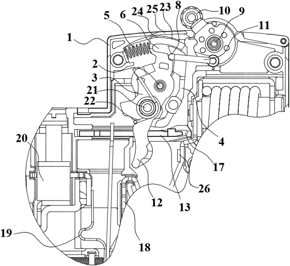
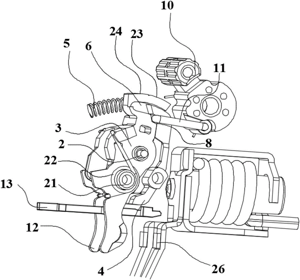
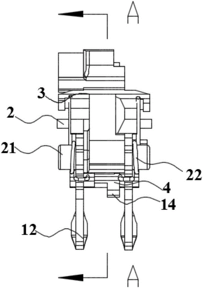
[0029] Below in conjunction with accompanying drawing and specific embodiment the present invention is described in further detail:

[0030] The operating mechanism of the electrical protection device in the present invention, such as figure 1 , figure 2 , image 3 and Figure 4 As shown, it includes a housing 1, a handle 10 is arranged in the housing 1 through the rotation of the handle shaft 9, a bracket 3 and a lock 4 are arranged in the housing 1 through the coaxial rotation of the bracket shaft 2, and the middle part of the lock 4 is provided with a convex The platform 41 and the lock catch 4 are rotated on the support shaft 2 through the boss hole 42 provided on the boss 41. The support 3 is provided with a middle recess 27, and the boss 41 is located in the middle recess 27. The support shaft 2 is provided with There is an axial torsion spring 7, one end of the axial torsion spring 7 is fixed on the inner wall of the middle recess 27, the other end of the axial tors...


PUM


Abstract

The invention relates to an operating mechanism of an electrical protection apparatus. The operating mechanism comprises a shell and a handle arranged in the shell, wherein a bracket and a lock catch are coaxially and rotationally arranged in the shell; an axial torsion spring is arranged on the bracket shaft, wherein the two ends of the axial torsion spring props against and presses the bracket and the lock catch respectively; one end of the bracket props against a bracket spring while the other end of the bracket spring props against the shell; a bracket end groove is formed in the side wall, propping against one end of the bracket spring, of the bracket; one end of the lock catch extends into the bracket end groove to form an opening-closing hole; the handle is in transmission connection with the opening-closing hole through a U-shaped pushing rod; when the handle is opened, one end of the push rod is locked through the opening-closing hole; when the handle is closed, the push rod is pushed to overcome the locking force of the opening-closing hole to slide to the bracket end groove and to push the bracket to rotate; a moving contact is connected with the relative end of one end, propping against the bracket spring, of the bracket; one end, far from the bracket end groove, of the lock catch props against a sliding block for limiting the rotation of the lock catch; and the sliding block is connected with a thermal releasing apparatus. The operating mechanism of the electrical protection apparatus is simple in structure, low in abrasion and long in service life.

Description

technical field [0001] The invention relates to the technical field of electrical protection devices, in particular to an operating mechanism of an electrical protection device. Background technique [0002] Electrical protection equipment is a device used to open and close circuits, that is, circuit breakers. The operating mechanism in electrical protection equipment not only needs to play a role in the normal circuit, but also needs to be timely and effectively opened and closed in the fault circuit, but in the circuit There are often short-circuit currents up to 6000A instantaneously. Conventional circuit breakers often cannot disconnect such circuits. There are several main reasons: [0003] 1. The operating mechanism cannot move quickly; the conventional operating mechanism takes up a large space, resulting in smaller other key components in the same housing, especially the arc extinguishing chamber and the arc extinguishing cover, and only a large enough arc extinguish...

Claims


Application Information

Patent Timeline
Patent Type & Authority Applications(China)
IPC IPC(8): H01H71/10H01H71/12
CPCH01H71/10H01H71/12H01H71/52
Inventor 李文杰
Owner YUEQING ZHISHUN ELECTRIC CO LTD
Why Eureka
Try Eureka